JBC PSS Multiaxis Rotative PCB Support Instruction Manual

This manual corresponds to the following reference:
PSS-A
Packing List
The following items are included:

Application
PSS is designed to support and fix PCBs to perform soldering and desoldering jobs with or without preheaters. JBC’s rotary support can work with JBC’s PHSE Preheater.
![]() Caution: Be careful not to pinch your fingers and take care when working with preheaters since metal surfaces of the support can be hot – especially the sliding guide and the spring guide.
Caution: Be careful not to pinch your fingers and take care when working with preheaters since metal surfaces of the support can be hot – especially the sliding guide and the spring guide.

Features
Horizontal Position

Inclined and Rotated Position

ESD Connections

Support Height Adjustment
The support incorporates a height adjustment mechanism inside the support legs. Choose between 3 different height levels.

To adjust the height, press the two lower push tabs upward at the same time and hold them pressed (1).

Lift the support while holding the tabs and let its feets drop down under their own weight (2).
While continuing to hold the lower tabs, place the support on the workplace and lower it until it reaches the desired height.
Release the tabs and the legs will automatically lock into position (3).
Note: Make sure that the components already mounted on the PCB do not come too close to the preheater plate.
If components are too close to the heating surface, they may be damaged. To avoid this, set the support height to level 2 or level 3 or set an adequate PCB holder angle to ensure sufficient distance.
Pay special attention when turning the PCB holder upside down.
Holder Positions
Default Position – without elevation and without rotation
By default, the sliding guide realease lever is located at the front and the push button for holder rotation on the right side.

Rotated Position
The PCB holder can be rotated all around (360º) in the horizontal position.
A single firm press onto the lateral push button (1) unlocks the holder position and keeps it unlocked to rotate freely. Rotate the holder into the desired position (2) and do a second firm press onto the lateral push button (1) to lock the holder in position.
A long soft press onto the lateral push button (1) keeps the holder postion unlocked as long as the button is pressed. Rotate the holder into the desired position (2) and release the push button (1) to rest the holder in position.
Note: To be able to rotate freely, the holder must have a free space of at least 300 mm in diameter.

Inclined Position
To place the holder in an inclined position, lift the rear end slightly upwards and hold the holder in the desired angular position (1).
With the other hand, turn the positioning lever upwards (2) and insert its stud into one of the openings of the positioning arm (3). Do the same on the opposite side to completely fix the holder in the desired position.
It is possible to choose between 4 different angular positions: 25º, 35º, 45º and 55º. Note: When working at 55º and level 3 height, the total height of PSS reaches 24.5 cm (up to 30 cm at 90º).
To return the holder to the horizontal position, set the lever to its horizontal position (4) – for a holder angle of 0º.

![]() Caution: When adjusting and changing the support positions, be aware that the metal surfaces may be hot.
Caution: When adjusting and changing the support positions, be aware that the metal surfaces may be hot.
PCB Placement
Loosen the knobs of the spring guide clamps (1), adjust their distance according to the PBC width (2) and tighten the knobs again. Clamps that are not needed can be slided to the side (3), or disassembled.
Loosen the knobs of the sliding guide clamps (4) and slide unneeded clamps aside (5).

Insert the PCB into the slots of the spring guide clamps (6) and into at least one clamp on the side of the sliding guide (7) and tighten the clamp knob (8).
Press the sliding guide tab against the PCB to move it together with the spring guide slightly backwards (9) until the sliding guide clicks into place (10).

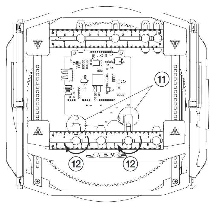
Now adjust the positions of the other sliding guide clamps to the PCB shape (11) and tighten their clamp knobs (12) after the adjustment.
The clamp knobs can be loosened and tightened by hand and/or by means of the provided Allen key.
The Allen key is stored on the side of the support and held in place by a built-in magnet.

Turning the PCB upside down
The PCB holder can be rotated by 180°.
This makes it possible to turn the PCB over in the clamped state without removing it, so that its underside is now pointing upwards.
This has the advantage that the PCB does not have to be repositioned if soldering is to be carried out on the top and on the bottom side of the PCB.
Note: Be aware that after turning it around, larger components may come too close to the preheater heating surface or table. If necessary, set a different support height or angle.
Horizontal PCB position

Inclined PCB position

Proceed in reverse order if you want to work on the top side of the PCB again.
Fast PCB Replacement
Removing the PCB
Push the PCB against the spring guide clamps (1) until the spring guide moves back slightly (2).
Now the PCB can be taken out of the clamps at the front end (3).

Placing another PCB
Position a new PCB inside the spring guide clamps (4). Push the spring guide backwards (against the spring force) until it moves slightly backwards (5).
Rotate the free side of the PCB downward (6) and position it in the slot clamps of the front area.
The spring guide automatically locks the PCB into position.

Maintenance

Before carrying out maintenance or storage, always allow the support to cool down.
– Check periodically that the Support is clean, especially the sliding guide axes.
– Use a damp cloth when cleaning. Alcohol can only be used to clean the metal parts
– Replace any defective or damaged piece. Use original JBC spare parts only.
– Repairs should only be performed by a JBC authorized technical service.
Safety
![]() It is imperative to follow safety guidelines to prevent electric shock, injury, fire or explosion.
It is imperative to follow safety guidelines to prevent electric shock, injury, fire or explosion.
– When using the support with a preheater unit, the temperature of accessible surfaces may remain high after the unit is turned off. Handle with care.
– Be careful not to pinch your fingers when operating the support.
– Be careful with the remains of liquid tin. In contact with the skin, it can cause burns.
– Avoid flux coming into contact with skin or eyes to prevent irritation.
– Be careful with the smoke produced when soldering.
– Keep your workplace clean and tidy. Wear appropriate protection glasses and gloves when working to avoid personal harm.
– This appliance can be used by children over the age of eight as well as persons with reduced physical, sensory or mental capabilities or lacking experience provided that they have been given adequate supervision or instruction concerning the use of the appliance and understand the hazards involved. Children must not play with the appliance.
– Maintenance must not be carried out by children unless supervised.
Specifications

![]()
Warranty
JBC’s 2 year warranty covers this equipment against all manufacturing defects, including the replacement of defective parts and labour.
Warranty does not cover product wear or misuse. In order for the warranty to be valid, equipment must be returned, postage paid, to the dealer where it was purchased.
![]() This product should not be thrown in the garbage.
This product should not be thrown in the garbage.
In accordance with the European directive 2012/19/EU, electronic equipment at the end of its life must be collected and returned to an authorized recycling facility.

Documents / Resources
 | JBC PSS Multiaxis Rotative PCB Support [pdf] Instruction Manual PSS-A, PSS Multiaxis Rotative PCB Support, PSS, Multiaxis Rotative PCB Support, Rotative PCB Support, PCB Support, Support |