導入
This manual provides detailed instructions for the DEWIN 8-Channel 24V Optocoupler Relay Module. This module is designed for various control applications, offering reliable switching capabilities with optocoupler isolation for enhanced safety and performance. It features a user-friendly interface for easy integration into microcontroller-based projects and industrial control systems.
製品の特徴
- 8-Channel Optocoupler Isolation: Each channel can be triggered by high or low level signals via jumper settings, ensuring robust isolation between control and load circuits.
- Humanized Interface Design: All interfaces are designed for direct connection using terminal cables, simplifying wiring. Standard interfaces allow direct control by microcontrollers.
- ステータスインジケータ: Equipped with a power indicator (green) and 8 relay status indicators (red) for easy monitoring of module and relay operation.
- 安定したパフォーマンス: Utilizes chip optocoupler isolation for strong driving capability and stable performance. Operating voltages available are 5V, 12V, and 24V (this model is 24V).
- Fault-Tolerant Design: Features a fault-tolerant design where the relay will not act even if the control line is disconnected, enhancing system reliability.
- Real Relays: Uses genuine relays with normally open (NO) interfaces.
仕様
| 仕様 | 価値 |
|---|---|
| モデル番号 | DEWINkhde43ygaz-03 |
| 重さ | 118g(4.2オンス) |
| Module Dimensions (L*W*H) | 141.5 x 50 x 18.5 mm (5.6 x 2 x 0.7 インチ) |
| ボルト穴径 | 3.1ミリメートル |
| Bolt Hole Spacing | 136×44.5ミリ |
| 営業巻tage | 24V直流 |
| Common Interface Load (AC) | AC 250V / 10A |
| Common Interface Load (DC) | DC30V/10A |
| トリガー電流 | 5mA |
| 連絡先 | 銅 |
| 連絡先の種類 | 通常閉(NC) |
| 取り付けタイプ | Screw Mount, DIN Rail Mount |
| コイル巻tage | 24V直流 |
| 最小スイッチング電圧tage | 24V直流 |
セットアップ手順
Follow these steps to correctly set up your DEWIN 8-Channel 24V Optocoupler Relay Module.
1.電源接続
Connect the power supply to the module using the designated terminals:
- DC +: Connect to the positive pole of your 24V DC power supply.
- DC-: Connect to the negative pole of your 24V DC power supply.

画像: トップダウン view of the DEWIN 8-Channel 24V Optocoupler Relay Module, highlighting the DC+ and DC- power input terminals, and the IN1-IN8 control input terminals. The module measures 141.5mm in length and 50mm in width.
2. Input Signal Connections (IN1-IN8)
The IN1 to IN8 terminals are used to control each individual relay. Connect your microcontroller or control signal source to these terminals. The relay can be triggered by either a high or low logic level, depending on the jumper settings.
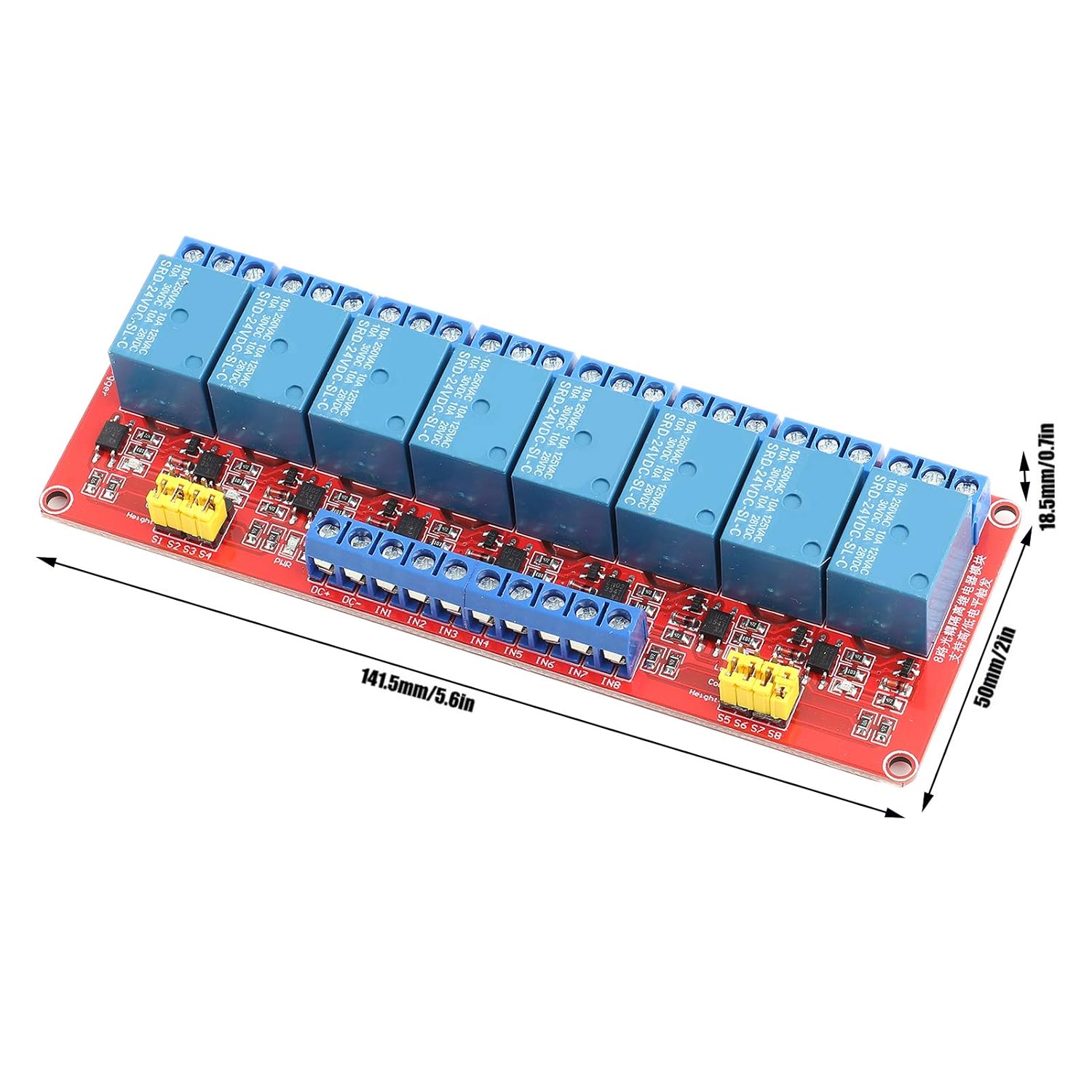
画像: 斜め view of the DEWIN 8-Channel 24V Optocoupler Relay Module, showing the input terminals (IN1-IN8) and the output relay terminals (NO, COM, NC) for each channel. Dimensions are indicated as 141.5mm (5.6in) length and 50mm (2in) width.
3. Relay Output Terminal Connections
Each relay channel provides three output terminals: Normally Open (NO), Common (COM), and Normally Closed (NC). These terminals allow for flexible connection to your load circuits.
- NO1-NO8: Normally Open interface. The relay is disconnected from COM when de-energized and connects to COM when energized.
- COM1-COM8: Common interface for the relay.
- NC1-NC8: Normally Closed interface. The relay is connected to COM when de-energized and disconnects from COM when energized.

画像: クローズアップ view of the DEWIN 8-Channel 24V Optocoupler Relay Module, showing the blue terminal blocks for the NO, COM, and NC connections for each of the eight relays. The yellow jumpers for high/low level trigger selection are also visible.
4. High/Low Level Trigger Selection (S1-S8 Jumpers)
The module allows you to select the trigger level for each relay channel independently using jumpers S1 through S8.
- To set a channel for low-level trigger: Connect the jumper between the "COM" pin and the "LOW" pin for that channel.
- To set a channel for high-level trigger: Connect the jumper between the "COM" pin and the "HIGH" pin for that channel.

画像: 上 view of the DEWIN 8-Channel 24V Optocoupler Relay Module, clearly showing the yellow jumpers (S1-S8) used to select between high and low-level triggering for each relay channel. The input and output terminals are also visible.
操作手順
Once the module is correctly wired and powered, you can operate the relays by sending appropriate control signals to the IN1-IN8 terminals.
- Triggering a Relay: Apply the selected trigger level (high or low, as set by the jumper) to the corresponding INx terminal. This will energize the relay, causing the COM terminal to switch its connection from NC to NO.
- De-triggering a Relay: Remove the trigger signal or apply the opposite logic level to the INx terminal. This will de-energize the relay, causing the COM terminal to switch its connection back from NO to NC.
- LEDインジケーター:
- の green power indicator LED illuminates when the module receives power.
- の red relay status LEDs (one for each channel) illuminate when their respective relay is energized (active).

画像: 斜めから view of the DEWIN 8-Channel 24V Optocoupler Relay Module, demonstrating its fault-tolerant design and stable performance. The red LEDs indicate the active status of individual relays.
メンテナンス
The DEWIN 8-Channel 24V Optocoupler Relay Module is designed for durability and requires minimal maintenance. To ensure optimal performance and longevity:
- 清潔に保ちます: Regularly inspect the module for dust or debris. Use a soft, dry brush or compressed air to gently clean the board. Avoid using liquids or solvents.
- 環境条件: モジュールは指定された温度および湿度範囲内で動作させてください。極端な温度、湿気、または腐食性環境への曝露は避けてください。
- 安全な接続: すべての配線接続が確実に固定され、腐食していないことを定期的に確認してください。接続が緩んでいると、断続的な動作や損傷につながる可能性があります。
- 過負荷を避ける: 最大電流と最大容量を超えないようにしてくださいtage ratings for the relay contacts (AC 250V/10A, DC 30V/10A). Overloading can damage the relays and shorten their lifespan.
トラブルシューティング
If you encounter issues with your relay module, refer to the following troubleshooting guide:
| 問題 | 考えられる原因 | 解決 |
|---|---|---|
| Module not powering on (Green LED off) | 電源なし、ボリュームが正しくありませんtage, reversed polarity, faulty power supply. | Verify 24V DC power supply connection to DC+ and DC-. Check power supply functionality. Ensure correct polarity. |
| Relay not activating (Red LED off when expected) | Incorrect trigger level, faulty input signal, incorrect jumper setting (High/Low), damaged relay. | Check the input signal (INx) from your microcontroller. Verify the jumper setting (S1-S8) matches the signal level. Ensure the input signal is within the module's specifications. |
| Relay always active or stuck (Red LED always on) | Stuck input signal, short circuit on input, damaged relay. | Disconnect the input signal to the INx terminal. If the relay remains active, the relay or module may be faulty. Check for any short circuits on the input line. |
| 負荷が切り替わらない | Incorrect load wiring, overloaded relay, faulty load, damaged relay contacts. | Verify connections to NO, COM, and NC terminals. Ensure the load's current and voltage do not exceed the relay's ratings (AC 250V/10A, DC 30V/10A). Test the load independently. |
保証とサポート
DEWIN products are manufactured to high-quality standards. While specific warranty details are not provided in this manual, please retain your proof of purchase for any warranty claims. For technical support, product inquiries, or assistance with troubleshooting beyond this guide, please contact DEWIN customer service through your retailer or the official DEWIN webサイト。
We are committed to providing reliable products and support to our customers.