DEWIN RDABCRYRA-GS99825
DEWIN 2.2KW 220V Variable Frequency Drive (VFD) Inverter User Manual
Model: RDABCRYRA-GS99825
1. Introduzione
This manual provides essential information for the safe and efficient operation of your DEWIN 2.2KW 220V Single-Phase Input, Three-Phase Output Variable Frequency Drive (VFD) Inverter. Please read this manual thoroughly before installation, operation, or maintenance to ensure proper usage and to prevent damage to the equipment or injury to personnel.
The DEWIN VFD is designed to control the speed and torque of three-phase asynchronous motors, offering precise control and energy efficiency for various industrial applications.
2. Informazioni sulla sicurezza
WARNING: Electrical shock hazard. Only qualified personnel should perform installation, wiring, and maintenance.
- Always disconnect power before performing any work on the VFD or connected equipment.
- Assicurare la corretta messa a terra del VFD e del motore.
- Do not touch electrical components immediately after power disconnection, as residual voltagPotrebbe essere presente. Attendere almeno 10 minuti affinché i condensatori si scarichino.
- Verificare che il volume di ingressotage matches the VFD's specifications.
- Proteggere il VFD da umidità, polvere e gas corrosivi.
- Non utilizzare il VFD con cavi o componenti danneggiati.
3. Caratteristiche principali
- Algoritmi di controllo multipli: Supports VF control for induction motors, open-loop magnetic flux vector control, standard open-loop control for permanent magnet synchronous motors, and open-loop vector control. Provides 150% starting torque at 0.5 Hz (sensorless vector control) for high torque, high precision, and wide speed control range.
- Rapid Current Limiting Function: Prevents frequent overcurrent alarms by quickly limiting current within a protected range during sudden load peaks or disturbances.
- Torque Limiting Function: Limits torque within a preset maximum range if the reference torque value exceeds the machine's maximum loadable torque, ensuring optimal system protection and mechanical efficiency.
- Independent Cooling Channel: Features a robust cooling fan and independent air duct design for efficient heat dissipation and low noise, ensuring long-term stable operation.
- Design intuitivo: Compact size and a removable front panel facilitate easy installation, operation, and wiring. Screw terminals provide convenient cable connections.

Figure 3.1: DEWIN VFD Inverter highlighting features such as motor protection, energy saving, frequency control, and strong security.
4. Specifiche tecniche
| Parametro | Valore |
|---|---|
| Numero di modello | RDABCRYRA-GS99825 |
| Potenza motore applicabile | 2.2 kW |
| Ingresso nominale voltage | Monofase 220V |
| Frequenza nominale di ingresso | Frequenza 50/60 Hz |
| Uscita Vol. Nominaletage | Trifase 220V |
| Frequenza di uscita (modalità bassa frequenza) | Frequenza |
| Corrente di uscita nominale | 10A |
| Materiale | Plastica ABS ignifuga |
| Metodo di installazione | Montaggio a parete |
| Livello di protezione | Grado di protezione IP20 |
| Metodo di raffreddamento | Ventola di raffreddamento |
| Peso dell'articolo | 830 grammi |
| Dimensioni del pacco | Dimensioni: 19 x 17 x 11 cm |

Figure 4.1: Physical dimensions and a summary of technical specifications for the DEWIN VFD Inverter.
5. Installazione
5.1 Installazione fisica
The DEWIN VFD is designed for wall-mounted installation. Ensure the mounting surface is stable and capable of supporting the unit's weight. Allow adequate clearance around the VFD for proper ventilation, especially for the cooling fan.

Figura 5.1: Posteriore view of the DEWIN VFD Inverter, showing the cooling fan and model information (Model: MS500-2S-2.2G, Power: 2.2KW, Input: 1PH AC220V 50/60Hz, Output: 3PH AC220V 0-320Hz 10A, Serial: JLS0022B21GB25080435).

Figura 5.2: In basso view of the DEWIN VFD Inverter, showing connection points.
5.2 Istruzioni per il cablaggio
Refer to the following diagrams for correct wiring of the VFD. Incorrect wiring can lead to equipment damage or safety hazards.
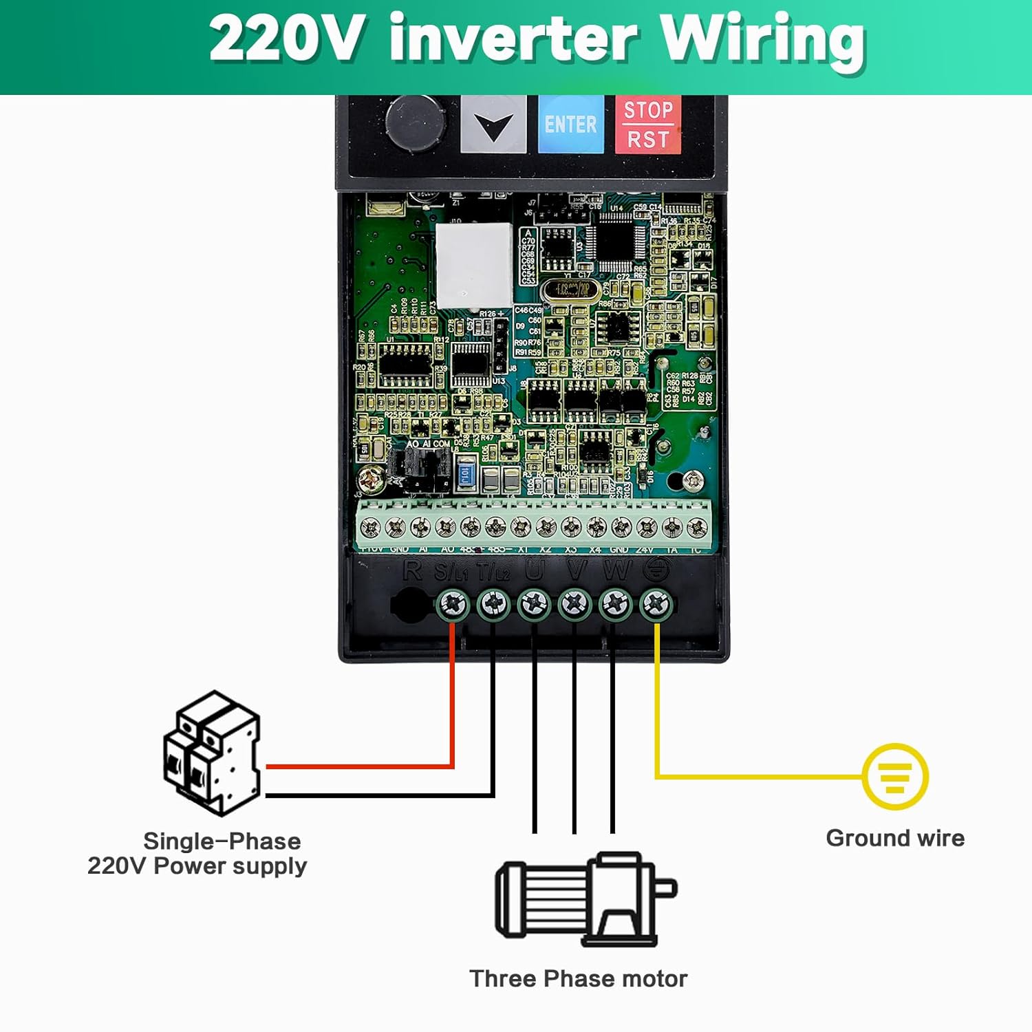
Figure 5.3: Wiring diagram for connecting a single-phase 220V power supply to the VFD and a three-phase motor. Ensure the ground wire is properly connected.

Figure 5.4: Detailed basic operation wiring diagram, including connections for breaker, power input (R, S(L1), T(L2)), multi-function input terminals (X1-X4, GND), external keyboard interface (J10), potentiometer (5K, 10K, 10V, A1, GND), analog output (AO1, GND), RS485 communication (485+, 485-), relay output (TA, TC), and three-phase asynchronous motor (U, V, W, Ground).
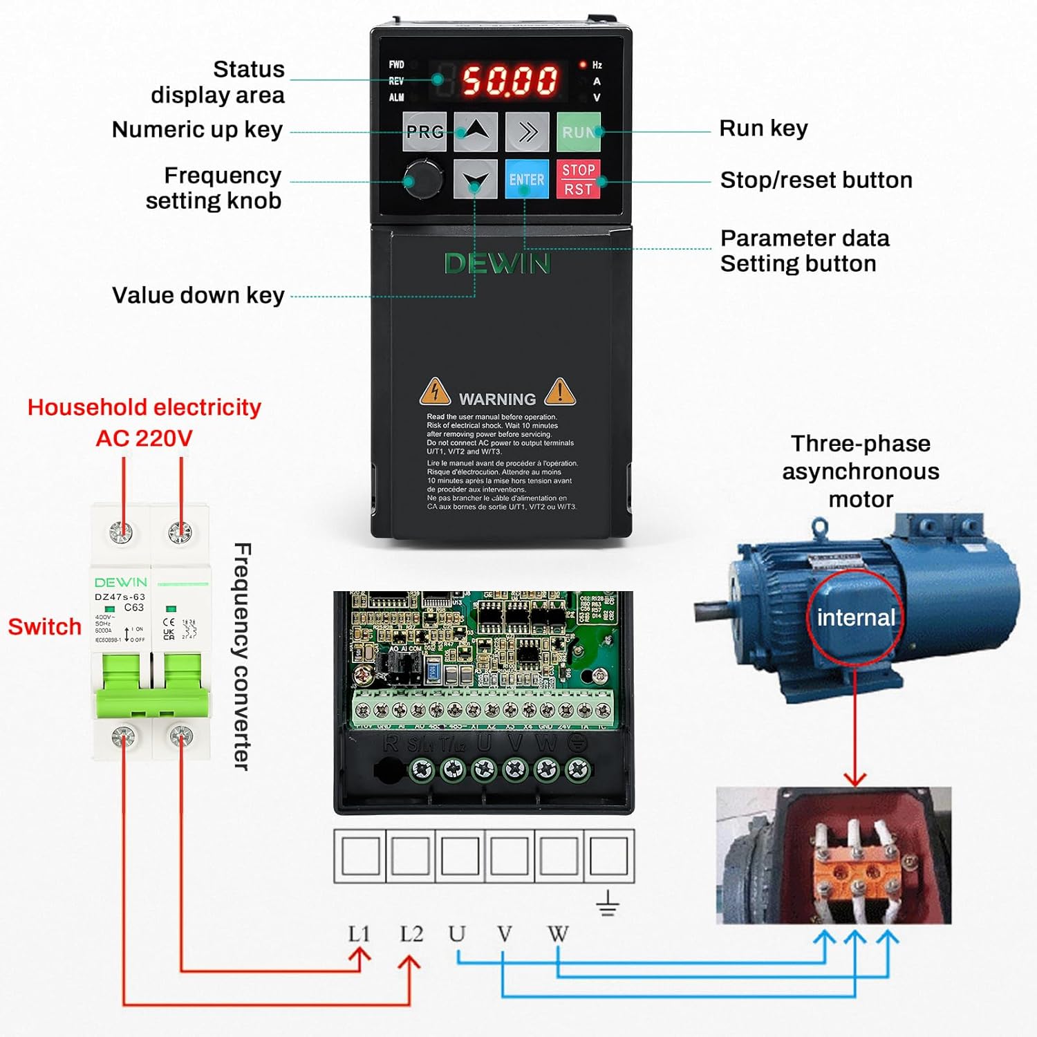
Figura 5.5: Oltreview showing the VFD control panel, connection to household AC 220V electricity via a switch, and wiring to a three-phase asynchronous motor.
6. Istruzioni per l'uso
6.1 Pannello di controllo Sopraview
The VFD features an intuitive control panel for easy operation and parameter setting.

Figura 6.1: dettagliata view of the VFD control panel, indicating the status display area, numeric up/down keys, frequency setting knob, parameter data setting button (PRG), run key (RUN), and stop/reset button (STOP/RST).
- Area di visualizzazione dello stato: Shows current operating frequency, voltage, current, and other status indicators.
- Pulsante PRG (Programma): Used to enter parameter setting mode and navigate through menus.
- Frecce su/giù: Used to adjust values or navigate menu options.
- Pulsante INVIO: Conferma le selezioni o le modifiche dei parametri.
- Pulsante RUN: Avvia il motore.
- Pulsante STOP/RST: Stops the motor and resets any active alarms.
- Manopola di impostazione della frequenza: Allows for manual adjustment of the output frequency.
6.2 Sequenza operativa di base
- Accensione: Ensure all wiring is correct and secure. Apply single-phase 220V power to the VFD. The display will illuminate.
- Imposta frequenza: Use the frequency setting knob or the Up/Down arrow keys to set the desired operating frequency.
- Avviamento del motore: Premere il tasto CORRERE button to start the motor. The VFD will ramp up to the set frequency.
- Arresto motore: Premere il tasto STOP/RST button to stop the motor. The VFD will ramp down and stop.
- Regolazione dei parametri: Premere il tasto PRG pulsante per accedere al menu di impostazione dei parametri. Utilizzare le frecce Su/Giù per navigare e ENTRARE to select and confirm. Refer to the detailed parameter manual (if provided separately) for advanced settings.
7. Manutenzione
Una manutenzione regolare garantisce la longevità e l'affidabilità del vostro VFD.
- Pulizia: Periodically clean the VFD's exterior and cooling fan vents to prevent dust accumulation, which can hinder heat dissipation. Use a soft, dry cloth. Do not use liquid cleaners.
- Ispezione: Controllare regolarmente tutti i collegamenti elettrici per verificarne la tenuta e l'eventuale presenza di segni di usura o danni. Verificare la presenza di rumori o odori insoliti durante il funzionamento.
- Ambiente: Ensure the operating environment remains within specified temperature and humidity ranges. Avoid exposure to direct sunlight, excessive vibration, or corrosive substances.
- Controllo della ventola: Verify that the cooling fan is operating freely and without obstruction.
Per qualsiasi manutenzione o riparazione interna, contattare personale di assistenza qualificato.
8. Risoluzione Dei Problemi
This section addresses common issues you might encounter with the VFD. For complex problems, consult a qualified technician.
8.1 Problemi comuni e soluzioni
| Problema | Possibile causa | Soluzione |
|---|---|---|
| VFD does not power on. | Nessuna alimentazione in ingresso; cablaggio errato; guasto interno. | Check power supply and circuit breaker. Verify input wiring. If problem persists, contact support. |
| Il motore non si avvia. | Incorrect frequency setting; motor wiring error; VFD in fault state; parameter misconfiguration. | Check frequency setting. Verify motor wiring (U, V, W). Check VFD display for error codes and reset if necessary. Review impostazioni dei parametri. |
| Overcurrent alarm (OC). | Sudden load increase; short circuit in motor or wiring; acceleration time too short. | Reduce load. Check motor and wiring for shorts. Increase acceleration time parameter. Utilize the rapid current limiting function. |
| Sovravoltage alarm (OV). | Ingresso voltage too high; deceleration time too short; regenerative load. | Controllare l'input voltage. Increase deceleration time parameter. Consider adding a braking resistor for regenerative loads. |
| Overheat alarm (OH). | Insufficient ventilation; ambient temperature too high; cooling fan malfunction. | Ensure proper ventilation and clear fan vents. Reduce ambient temperature. Check cooling fan operation. |
If you encounter an issue not listed here or cannot resolve a problem, please contact DEWIN customer support.
9. Assistenza clienti
For technical assistance, warranty information, or service inquiries, please contact DEWIN customer support through the retailer where the product was purchased or visit the official DEWIN websito.
When contacting support, please have your model number (RDABCRYRA-GS99825) and purchase date available.
Ask a question about this manual
Ask about setup, troubleshooting, compatibility, parts, safety, or missing instructions. Manuals+ will review the question and use this page’s manual context to help answer it.