1. Introduzione
This user manual provides comprehensive instructions for the safe and efficient operation, installation, and maintenance of your XWJNE 4000W Pure Sine Wave Power Inverter. This device is designed to convert 48V DC power from batteries into 120V AC power, suitable for a wide range of applications including home, RV, truck, and off-grid solar power systems. Please read this manual thoroughly before using the inverter to ensure proper functionality and to prevent damage to the unit or connected appliances.

Image: The XWJNE 4000W Pure Sine Wave Power Inverter, showcasing its main unit, heavy-duty battery cables (red for positive, black for negative), and the remote control display unit.
2. Istruzioni di sicurezza
Osservare sempre le seguenti precauzioni di sicurezza per evitare lesioni personali o danni all'inverter e alle apparecchiature collegate:
- Assicurarsi che l'inverter sia installato in un'area ben ventilata, lontano dalla luce solare diretta, da fonti di calore e da materiali infiammabili.
- Non esporre l'inverter ad acqua, pioggia o umidità eccessiva.
- Connect the inverter only to a 48V DC power source. Connecting to an incorrect voltage causerà danni.
- Ensure all connections are tight and secure to prevent loose connections that can cause overheating or sparks.
- Non utilizzare l'inverter se è caduto o è danneggiato.
- Tenere i bambini lontani dall'inverter e dai suoi collegamenti.
- Scollegare sempre la batteria prima di effettuare qualsiasi operazione di manutenzione o pulizia.
- L'inverter genera un'alta tensionetage AC power; treat it with extreme caution.
- Non tentare di smontare o modificare l'inverter. Per qualsiasi intervento di manutenzione, rivolgersi a personale qualificato.
- Ensure the total power consumption of connected appliances does not exceed the inverter's rated output (4000W continuous, 8000W peak).

Immagine: Un interno view of the inverter highlighting its six safety protection functions: low-voltage protection, output short circuit protection, overvoltage protection, overpower protection, load shock protection, and overtemperature protection.
3. Contenuto della confezione
Verificare che tutti gli articoli siano presenti nel pacco:
- XWJNE 4000W Pure Sine Wave Power Inverter
- Car Battery Cables (2.62ft 7AWG positive and negative)
- Remote Controller (with 16.4ft cable)
- Manuale di istruzioni
- Chiave
- Ground Wire (1.64ft)
- Fuses (7 x 40A 32V)
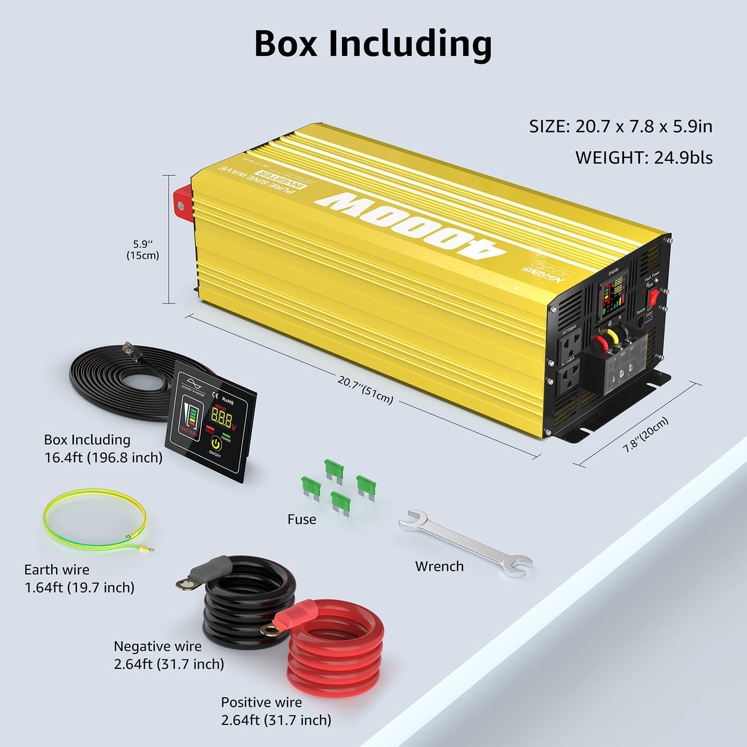
Image: A visual representation of the XWJNE 4000W inverter and its complete set of accessories, including the remote control, battery cables, ground wire, fuses, and a wrench, along with product dimensions.
4. Caratteristiche del prodotto
- Uscita ad alta potenza: Provides a stable 4000W continuous power output (8000W peak) from 48V DC to 120V AC.
- Tecnologia a onda sinusoidale pura: Delivers clean, stable power comparable to utility grid electricity, suitable for sensitive electronics like laptops, lights, TVs, refrigerators, and stereos, ensuring quiet operation without humming sounds.
- Protezione completa: Equipped with 6 types of protection: undervoltage, voltage, overload, over-temperature, short circuit, and reverse connection protection for enhanced safety.
- Display LED e telecomando: Features an LED screen for real-time status monitoring and a remote controller with a 16.4ft cable for convenient operation in various settings.
- Porte di uscita multiple: Includes 2 x 120V AC output ports, 1 x USB port (5V 2.4A), and 1 x AC terminal board.
- Costruzione durevole: Built with aluminum and plastic for a sturdy structure that protects against impacts and aids in heat dissipation.
- Sistema di raffreddamento intelligente: Integrated smart fans automatically activate when the internal temperature is too high or load reaches half capacity, ensuring optimal operating conditions and low noise.

Image: A diagram illustrating the smooth, consistent waveform of a pure sine wave compared to a modified sine wave, emphasizing the inverter's >90% conversion efficiency and 40% power consumption reduction.
5. Componenti finitiview
Familiarize yourself with the different parts of your inverter:

Image: A detailed diagram pointing out key components of the inverter, including the Power Switch, Fault Indicator Lamp, Remote Controller port, LED Display, AC Output ports (2x 15A), Earth Wire terminal, AC Terminal Board (45A), USB port (5V 2.4A 12W), Positive and Negative DC Terminals, and Intelligent Cooling Fans.
- Interruttore di alimentazione: Accende/spegne l'inverter.
- Indicatore di guasto Lamp: Si illumina per indicare un errore o una modalità di protezione.
- Porta del telecomando: Collega il telecomando cablato.
- Display a LED: Mostra il volume in tempo realetage, battery level, frequency, and load percentage.
- Porte di uscita CA: Prese standard da 120 V CA per il collegamento degli elettrodomestici.
- Terminale del filo di terra: Per la messa a terra dell'inverter.
- AC Terminal Board: For hardwiring AC loads.
- Porta USB: Uscita 5V 2.4A per la ricarica di dispositivi USB.
- DC Input Terminals (Positive/Negative): Connect to the 48V DC battery bank.
- Ventole di raffreddamento intelligenti: Si attivano automaticamente per dissipare il calore e mantenere la temperatura di esercizio ottimale.
6. Configurazione e installazione
Un'installazione corretta è fondamentale per le prestazioni e la sicurezza dell'inverter.
6.1 Collegamento della batteria
The inverter requires a 48V deep cycle battery bank. Ensure the battery capacity is sufficient for your power needs. For a 4000W inverter, a minimum of 4 x 100Ah 12V batteries (wired in series for 48V) or equivalent 48V battery is recommended.

Image: Two diagrams illustrating connection methods: one for direct battery connection for independent use, and another for integration into an off-grid solar system with solar panels and an MPPT charge controller.
- Assicurarsi che l'interruttore di alimentazione dell'inverter sia in posizione OFF.
- Connect the positive (+) battery cable (red) to the positive (+) terminal of the battery bank and the positive (+) DC input terminal on the inverter.
- Connect the negative (-) battery cable (black) to the negative (-) terminal of the battery bank and the negative (-) DC input terminal on the inverter.
- Assicurarsi che tutti i collegamenti siano ben saldi e sicuri. Collegamenti allentati possono causare calore eccessivo e danni.
- Connect the ground wire from the inverter's earth terminal to a proper ground point (e.g., vehicle chassis, earth rod).
6.2 Remote Controller Installation
The remote controller allows for convenient operation from a distance.
- Locate the remote control port on the inverter.
- Connect the remote controller cable to this port.
- The remote controller can be mounted in a suitable location using screws, as it is designed for embedding.

Image: The remote operation switch conveniently installed in a compact space, such as inside an RV, demonstrating its suitability for use in cramped or narrow environments.
7. Funzionamento
7.1 Accensione/Spegnimento
- Ensure all connections are secure, then switch the inverter's power button to the ON position.
- The LED display will illuminate, showing battery voltage, volume di uscitatage, e altri parametri operativi.
- To turn off the inverter, switch the power button to the OFF position.
7.2 Collegamento degli elettrodomestici
Plug your 120V AC appliances into the inverter's AC output ports or connect them to the AC terminal board. Ensure the total wattage of all connected appliances does not exceed 4000W.
7.3 Comprensione del display LED
Il display LED fornisce informazioni essenziali sullo stato dell'inverter:
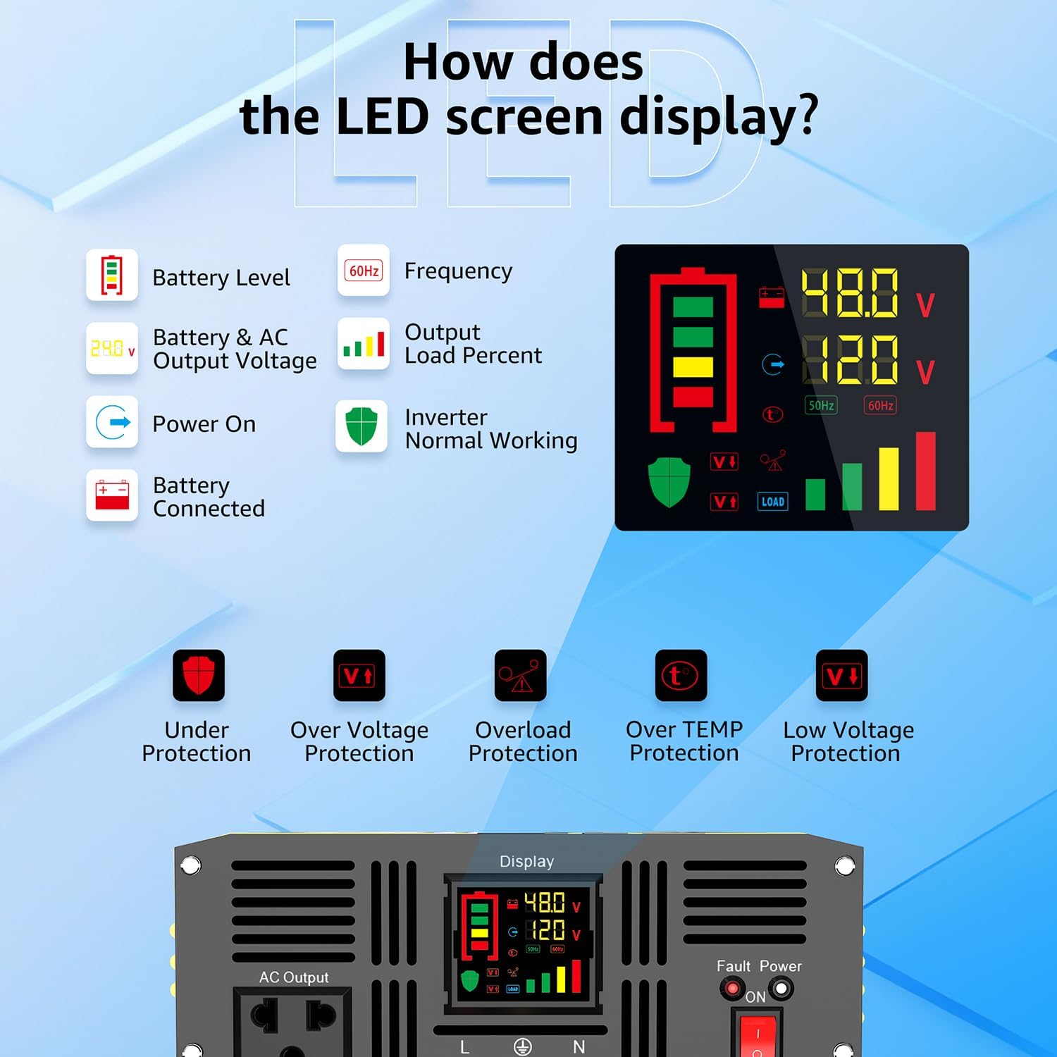
Image: A visual guide to the inverter's LED display, explaining indicators such as Battery Level, Frequency, Output Load Percent, Power On status, Battery Connected status, and Inverter Normal Working status. It also shows icons for Under Protection, Over Voltage Protection, Overload Protection, Over TEMP Protection, and Low Voltage Protezione.
- Livello della batteria: Indicates the remaining charge in your battery bank.
- Frequenza: Visualizza la frequenza di uscita (ad esempio, 60 Hz).
- Output Load Percent: Mostra la percentualetage della capacità dell'inverter attualmente utilizzata.
- Ingresso/Uscita Voltage: Visualizza il volume dell'ingresso CCtage dalla batteria e dal volume di uscita CAtage.
- Indicatori di protezione: Icons will light up to indicate specific protection modes (e.g., Under Voltage, Overload, Over Temperature).
8. Manutenzione
Una manutenzione regolare garantisce la longevità e le prestazioni ottimali del vostro inverter.
8.1 Pulizia generale
- Mantenere l'inverter pulito e privo di polvere e detriti. Utilizzare un panno asciutto per pulire la parte esterna.
- Assicurarsi che le prese d'aria della ventola di raffreddamento non siano ostruite per consentire un corretto flusso d'aria.

Image: A close-up of the inverter's two high-efficiency cooling fans, illustrating their automatic activation at 50 degrees Celsius or half load, and their low decibel operation (less than 60dB when on, less than 20dB when off).
8.2 Sostituzione del fusibile
If the inverter stops working due to an internal fuse issue, you may need to replace it. Always use fuses of the correct rating (40A 32V).
Video: This video demonstrates the step-by-step process of replacing the fuse in the XWJNE Pure Sine Wave Power Inverter. It shows how to safely open the unit, locate the fuses, remove the old fuse, and install a new one.
- Ensure the inverter is completely disconnected from the battery and all loads.
- Carefully remove the screws securing the upper cover of the inverter.
- Gently open the upper cover to expose the internal components.
- Locate the internal fuses (typically orange 40A fuses).
- Using a suitable tool (e.g., needle-nose pliers), carefully remove the blown fuse.
- Insert a new 40A 32V fuse into the slot.
- Replace the upper cover and secure it with the screws.
9. Risoluzione Dei Problemi
The LED display provides fault codes to help diagnose issues. Refer to the table below for common problems and their solutions.

Image: A visual guide to the inverter's fault display, listing various fault codes (F01-F13) and their corresponding meanings, such as Parameter Configuration Fault, Sampling Circuit Fault, DC Bus Voltage too Low, Output Overload, Over-temperature Protection, and Battery Overvoltage/Sottovoltage.
| Codice | Descrizione | Possibile causa/soluzione |
|---|---|---|
| F01 | Parameter Configuration Fault | Internal error. Contact support. |
| F02 | Sampling Circuit Fault | Internal error. Contact support. |
| F03 | Volume bus CCtage troppo basso | Volume della batteriatage is too low. Recharge or replace battery. |
| F04 | Other power source connected with the output cables | Ensure no other AC source is connected to the inverter's output. |
| F05 | Cortocircuito in uscita | Check connected appliances and wiring for short circuits. Disconnect and restart. |
| F06 | Sovracorrente in uscita | Reduce load. Disconnect some appliances. |
| F07 | Sovraccarico di uscita | Reduce total connected load below 4000W. |
| F08 | Protezione da sovratemperatura | Ensure proper ventilation. Allow inverter to cool down. Check fan operation. |
| F09 | Other power source connected with the output cables | Same as F04. |
| F10 | Sovraccarico batteriatage | Ingresso DC voltage is too high. Check battery charging system. |
| F11 | Sovravol. bus CCtage | Overvol. internotage. Contact support. |
| F12 | Batteria Undervoltage | Volume della batteriatage is too low. Recharge or replace battery. |
| F13 | Data Read Error | Internal communication error. Contact support. |
10. Specifiche
| Caratteristica | Dettaglio |
|---|---|
| Numero di modello | 24IVA-4KW-48V-110 |
| Potenza nominale | 4000W |
| Potenza di picco | 8000W |
| Ingresso CC Voltage | 48V CC |
| Volume di uscita CAtage | 120 V CA |
| Forma d'onda di uscita | Onda sinusoidale pura |
| Efficienza | >90% |
| Dimensioni del prodotto | 12.01 x 19.21 x 25 pollici |
| Peso dell'articolo | 19.2 libbre |
| Uscita USB | 5V 2.4A |
| Usi consigliati | Home, Off-Grid, RV, Truck, Vehicle |
11. Garanzia e supporto
XWJNE products are designed for reliability and performance. For warranty information, technical support, or service inquiries, please refer to the contact information provided with your purchase or visit the official XWJNE websito. Il nostro team del servizio clienti è a tua disposizione per rispondere a qualsiasi domanda o problema tu possa incontrare.