
KEYENCE IL-300
Manuale utente del sensore laser KEYENCE IL-300
Model: IL-300 | Brand: KEYENCE (Manufactured by Vanky Industry)
1. Introduzione
The KEYENCE IL-300 is a high-precision laser displacement sensor designed for accurate measurement in various industrial applications. This manual provides essential information for the proper setup, operation, and maintenance of the IL-300 sensor to ensure optimal performance and longevity.
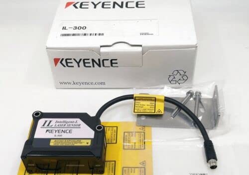
Figure 1.1: The KEYENCE IL-300 Laser Sensor, showing the main unit, connecting cable, and mounting bracket, alongside its product packaging.
2. Specifiche
The following table details the technical specifications of the KEYENCE IL-300 Laser Sensor.

Figura 2.1: Oltreview of KEYENCE IL-300 technical specifications.
| Parametro | Specificazione |
|---|---|
| Modello | IL-300 |
| Distanza di riferimento | 300 mm (11.81") |
| Campo di misura | 160 to 450 mm (6.30" to 17.72") |
| Tipo di sorgente luminosa | Red semiconductor laser, wavelength: 655 nm (visible light) |
| Classe laser | Class 2 (FDA (CDRH) Part1040.10)*1, Class 2 (IEC 60825-1) |
| Produzione | 560 µW |
| Spot Diameter (at standard distance) | Approx. ø0.5 mm (ø0.02") |
| Linearità | ±0.25% of F.S. (160 to 440 mm / 6.30" to 17.32")*2*3 |
| Ripetibilità | 30 µm*4 |
| Samptasso di ling | 0.33/1/2/5 ms (4 levels available) |
| Operation Status Indicators | Laser emission warning indicator: Green LED, Analog range indicator: Orange LED, Reference distance indicator: Red/Green LED |
| Caratteristiche della temperatura | 0.08% of F.S./°C*5 |
| Resistenza ambientale | |
| Valutazione dell'involucro | Grado di protezione IP67 |
| Grado di inquinamento | 3 |
| Luce ambientale | Incandescenteamp: 5,000 lux*6 |
| Temperatura ambiente | -10 to +50 °C (14 to 122 °F) (No condensation or freezing) |
| Umidità relativa | Dal 35 all'85 % di umidità relativa (senza condensa) |
| Resistenza alle vibrazioni | Da 10 a 55 Hz, doppio amplitude 1.5 mm (0.06"), 2 hours in each of the X, Y, and Z directions |
| Materiale | Housing material: PBT, Metal parts: SUS304, Packing: NBR, Lens cover: Glass, Cable: PVC |
| Peso | Circa 135 g |
*1 The laser classification for FDA (CDRH) is implemented based on IEC 60825-1 in accordance with the requirements of Laser Notice No.50.
*2 Value when measuring the KEYENCE standard target (white diffuse object).
*3 F.S. of each model is as follows. IL-030: ±5 mm ±0.20" IL-065: ±10 mm ±0.39" IL-100: ±20 mm ±0.79" IL-300: ±140 mm ±5.51" IL-600: ±400 mm ±15.75" IL-2000: +1000 to -1500 mm 39.37" to -59.05"
*4 Value when measuring the KEYENCE standard target (white diffuse object) at the reference distance, sampling rate: 1 ms, and average number of times: 128. For the IL-300/IL-600, the sampling rate is 2 ms.
*5 F.S. of each model is as follows. IL-030: ±5 mm ±0.20" IL-065: ±10 mm ±0.39" IL-100: ±20 mm ±0.79" IL-300: ±140 mm ±5.51" IL-600: ±400 mm ±15.75"
*6 Value when the sampling rate is set to 2 ms or 5 ms.
3. Configurazione e installazione
Proper installation is crucial for the accurate and reliable operation of the IL-300 sensor. Follow these guidelines for setup.
3.1 Disimballaggio e ispezione
- Carefully remove the sensor and all accessories from the packaging.
- Inspect all components for any signs of damage during transit. If any damage is found, contact your supplier immediately.
- Verificare che tutti i componenti elencati nella lista di imballaggio siano presenti.

Figure 3.1: The IL-300 sensor unit, showing the attached cable and separate mounting hardware.
3.2 Montaggio del sensore
The IL-300 sensor should be mounted securely to a stable surface using the provided mounting bracket and screws. Ensure the sensor is positioned to allow for the target to be within the specified measurement range (160 to 450 mm) and ideally at the reference distance (300 mm) for optimal performance.
- Attach the mounting bracket to the sensor using the appropriate screws.
- Secure the sensor assembly to the desired location, ensuring it is stable and free from vibration.
- Consider the ambient light conditions; while the sensor has resistance up to 5,000 lux (incandescent lamp), direct strong light sources should be avoided if possible.

Figura 3.2: Posteriore view of the IL-300 sensor, illustrating the cable connection point.
3.3 collegamenti elettrici
Connect the sensor's cable to the appropriate power supply and control unit according to your system's wiring diagram. Ensure all connections are secure to prevent intermittent operation or damage.
- Verificare il vol dell'alimentatoretage matches the sensor's requirements.
- Assicurare una corretta messa a terra per evitare interferenze elettriche.
- Avoid routing sensor cables near high-voltage lines or noise-generating equipment.
4. Funzionamento
Once installed and connected, the IL-300 sensor is ready for operation. The sensor provides an analog output corresponding to the measured distance.
4.1 Accensione
Apply power to the sensor. Observe the operation status indicators on the sensor unit.

Figura 4.1: primo piano view of the IL-300 sensor's indicator lights (CENTER, A. RANGE, LASER).
4.2 Comprensione degli indicatori
- Laser Emission Warning Indicator (Green LED): Illuminates when the laser is emitting.
- Analog Range Indicator (Orange LED): Indicates if the measured distance is within the analog output range.
- Reference Distance Indicator (Red/Green LED): Changes color to indicate if the target is at or near the reference distance. Consult the full product manual for specific color meanings.
4.3 Principi di misurazione
The IL-300 uses a red semiconductor laser to measure the distance to a target. The sensor outputs an analog signal proportional to this distance. Ensure the target surface is suitable for laser measurement (e.g., not highly reflective or transparent without proper setup).
- The optimal measurement is achieved when the target is at the reference distance of 300 mm.
- The sensor can measure within a range of 160 mm to 450 mm.
- Le sampling rate can be adjusted (0.33/1/2/5 ms) depending on the application's speed requirements.
5. Manutenzione
The KEYENCE IL-300 sensor is designed for robust industrial use, but regular maintenance ensures its long-term reliability and accuracy.
- Pulizia: Periodically clean the lens cover (glass) with a soft, lint-free cloth. If necessary, use a mild, non-abrasive cleaning solution. Avoid harsh chemicals that could damage the lens or housing.
- Ispezione dei cavi: Regularly inspect the sensor cable for any signs of wear, cuts, or damage. Damaged cables can lead to intermittent operation or complete failure.
- Sicurezza del montaggio: Check that the sensor remains securely mounted and that all mounting screws are tight. Vibration can loosen connections over time.
- Condizioni ambientali: Ensure the operating environment remains within the specified temperature (-10 to +50 °C) and humidity (35 to 85 % RH, non-condensing) ranges. While the sensor has an IP67 enclosure rating, protecting it from excessive dust and moisture will extend its lifespan.
6. Risoluzione Dei Problemi
If you encounter issues with your IL-300 sensor, refer to the following common troubleshooting steps before contacting support.
| Problema | Possibile causa | Soluzione |
|---|---|---|
| Sensor not powering on / No indicators lit | No power supply; Incorrect wiring; Damaged cable. | Controllare i collegamenti di alimentazione e il volumetage. Verify wiring according to the system diagram. Inspect cable for damage. |
| Inaccurate or unstable measurements | Target outside measurement range; Dirty lens; Excessive vibration; Unsuitable target surface; Ambient light interference. | Ensure target is within 160-450 mm. Clean the lens cover. Secure mounting to reduce vibration. Consider target material/color. Reduce strong ambient light. |
| Laser emission warning indicator (Green LED) not lit | Sensor malfunction; Power issue. | Verify power supply. If power is present and other indicators function, the sensor may require service. |
| Analog range indicator (Orange LED) not lit or flickering | Target outside analog output range; Sensor not properly calibrated for application. | Adjust target position to be within the optimal analog range. Consult the full product manual for calibration procedures if applicable. |
If the problem persists after attempting these solutions, please contact your supplier or KEYENCE technical support for further assistance.
7. Garanzia e supporto
For information regarding the warranty period and terms for your KEYENCE IL-300 Laser Sensor, please refer to the documentation provided at the time of purchase or contact your authorized KEYENCE distributor or the seller (Vanky Industry).
Technical support is available from KEYENCE or your supplier for assistance with installation, operation, and troubleshooting. When contacting support, please have your product model (IL-300) and any relevant serial numbers or purchase details ready.
Ask a question about this manual
Ask about setup, troubleshooting, compatibility, parts, safety, or missing instructions. Manuals+ will review the question and use this page’s manual context to help answer it.