EPEVER LS1024B
EPEVER LandStar LS1024B PWM Solar Charge Controller User Manual
Model: LS1024B | Brand: EPEVER
1. Introduzione
This manual provides detailed instructions for the installation, operation, and maintenance of the EPEVER LandStar LS1024B PWM Solar Charge Controller. This device is designed to manage the power flow from a solar panel to a battery bank and DC load, ensuring efficient and safe charging and discharging.
The LS1024B controller features automatic 12V/24V system voltage recognition, multiple charging options (Sealed, Gel, Flooded, User-defined), and various load working modes. It incorporates industrial-standard MOSFET open architecture for reliable performance and comprehensive electronic protections.
2. Informazioni sulla sicurezza
Leggere attentamente tutte le istruzioni e le avvertenze prima dell'installazione e dell'uso. Il mancato rispetto di queste istruzioni può causare scosse elettriche, incendi o lesioni gravi.
- Assicurarsi che tutti i cavi siano correttamente polarizzati e collegati saldamente.
- Installare il controller in un'area ben ventilata, lontano da materiali infiammabili.
- Non smontare o tentare di riparare il controller da soli. Contattare personale qualificato per l'assistenza.
- Always disconnect the solar panel and battery power before installing or moving the controller.
- A fuse should be installed on the battery positive line, as close to the battery as possible (suggested distance within 150mm).
3. Caratteristiche del prodotto
- Support 4 Charging Options: Sealed, Gel, Flooded, and User-defined.
- Multiple Load Working Modes: Manual Control, Light ON/OFF, Light On+Timer, and Time Control.
- Equipped with industrial standard MOSFET open architecture, ensuring no mechanical switch.
- 12V/24V Auto Work, Max PV 50V input, and Real-time Energy Statistics.
- High Efficient PWM Charging Method and convenient checking via three LED indicators.
4. Componenti e indicatori
Familiarize yourself with the various parts and indicators of the LS1024B controller.
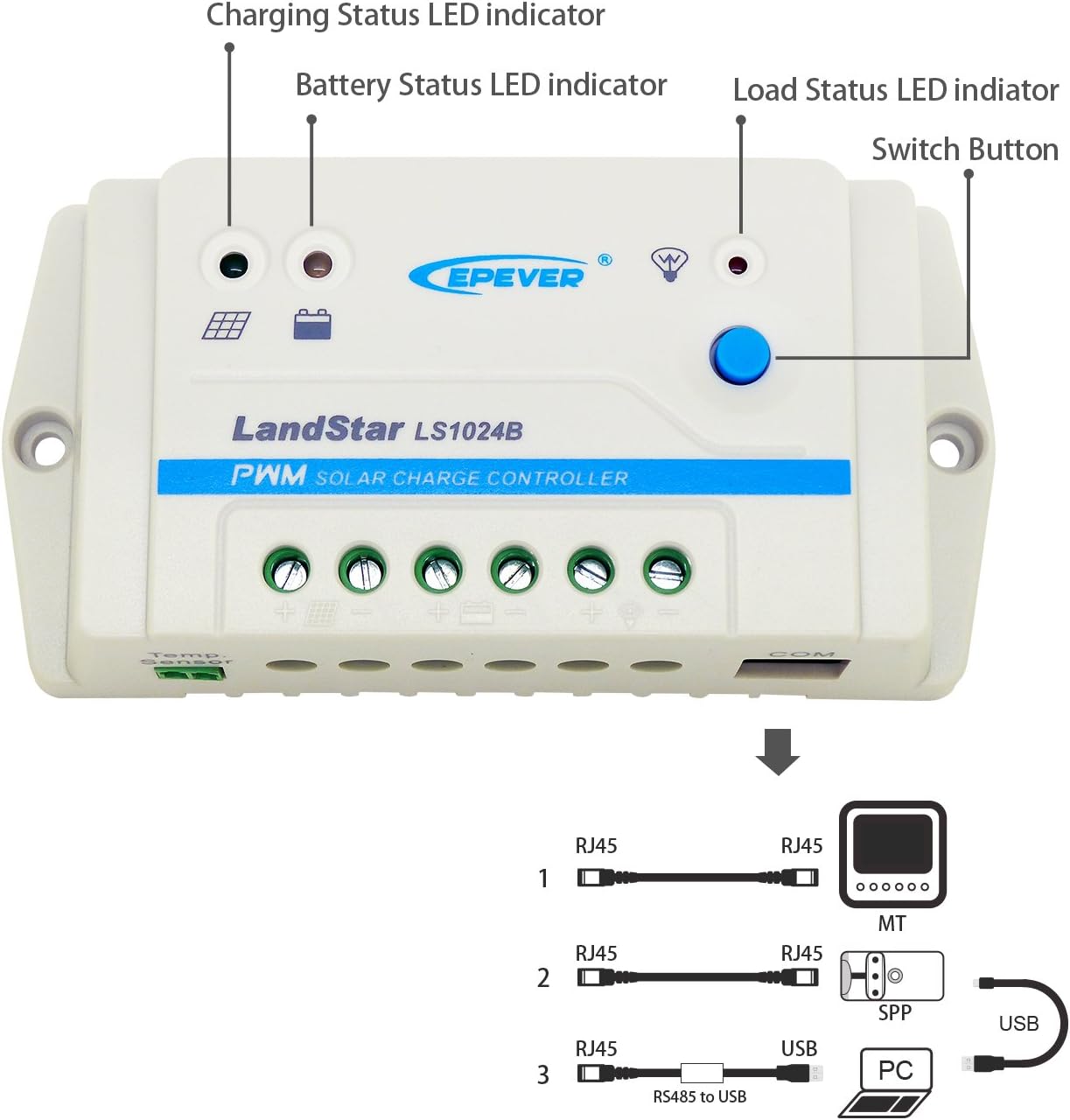
Figura 4.1: Davanti view of the LS1024B controller with key components labeled.
- Indicatore LED dello stato di carica: Shows the status of solar charging.
- Indicatore LED dello stato della batteria: Displays the battery's charge level.
- Indicatore LED dello stato del carico: Indica lo stato dell'uscita del carico CC.
- Interruttore: Used for controlling the load output and navigating settings.
- Terminali fotovoltaici: Connect to the solar panel.
- Terminali della batteria: Connect to the battery bank.
- Terminali di carico: Connect to the DC load.
- Temp. Sensor Port: For connecting an optional remote temperature sensor.
- Porta COM (RJ45): For communication with external devices like an MT50 remote meter or PC via an RS485 to USB cable.

Figura 4.2: Top-down view of the EPEVER LS1024B Solar Charge Controller, showing the terminals and indicators clearly.

Figura 4.3: Metter il fondo a view of the EPEVER LS1024B Solar Charge Controller, showing the mounting holes and heat sink design.
5. Configurazione e installazione
Follow these steps for proper installation of your solar charge controller.
5.1 Sequenza di cablaggio
It is crucial to connect the components in the correct sequence to prevent damage to the controller or other system components. Always connect the battery first.

Figura 5.1: Recommended wiring sequence for the LS1024B controller.
- Collegare la batteria: Connect the battery to the charge controller's battery terminals (marked with a battery symbol). Pay close attention to polarity (+ and -). The battery indicator on the controller should turn green. If not, refer to the troubleshooting section. A battery fuse should be installed on the positive line, as close to the battery as possible (suggested distance within 150mm).
- Collegare il pannello solare: Connect the solar panel to the charge controller's PV terminals (marked with a solar panel symbol). Ensure correct polarity.
- Collegare il carico: Connect the DC load to the charge controller's load terminals (marked with a light bulb symbol). Ensure correct polarity.
Importante: Disconnect in the reverse order: first the solar panel, then the load, and finally the battery.
5.2 Montaggio
Mount the controller vertically on a flat, solid surface, ensuring adequate air circulation around the unit for heat dissipation. Avoid direct sunlight, high temperatures, and humid environments.
6. Istruzioni per l'uso
6.1 Indicatori LED
The LS1024B features three LED indicators to display system status:
- Charging Status LED (Solar Panel Icon):
- Green Solid: Charging.
- Green Flashing: Float charging.
- Off: No charging.
- Battery Status LED (Battery Icon):
- Green Solid: Battery full.
- Green Flashing: Battery normal.
- Red Solid: Battery low voltage.
- Red Flashing: Battery over-discharge.
- Load Status LED (Light Bulb Icon):
- Green Solid: Load ON.
- Off: Load OFF.
- Red Flashing: Load overload/short circuit.
6.2 Load Control Button
The blue button on the controller is used to control the DC load output and cycle through load working modes.
- Pressione breve: Toggles the load output ON/OFF (in Manual Control mode).
- Pressione lunga (5 secondi): Cycles through the load working modes. The Load Status LED will flash to indicate the current mode.
6.3 Modalità di lavoro del carico
The LS1024B supports several load working modes:
- Controllo manuale: Load is turned ON/OFF by pressing the button.
- Luce accesa/spenta: Il carico si accende al tramonto e si spegne all'alba.
- Light On + Timer: Load turns ON at dusk and stays ON for a set number of hours.
- Controllo del tempo: Load turns ON and OFF based on pre-set times (requires external programming via PC software or MT50 remote meter).
Note: Detailed configuration of "Light On + Timer" and "Time Control" modes typically requires an external communication device (e.g., MT50 remote meter or PC software via RS485 to USB cable).
Figura 6.1: The COM port (RJ45) on the LS1024B for connecting communication accessories.
7. Manutenzione
Una manutenzione regolare garantisce prestazioni ottimali e longevità del regolatore di carica solare.
- Pulizia: Mantenere il controller pulito e privo di polvere e detriti. Utilizzare un panno asciutto per la pulizia.
- Connessioni: Controllare periodicamente tutti i collegamenti elettrici per verificarne la tenuta e la corrosione. Collegamenti allentati possono causare surriscaldamento e danni.
- Ventilazione: Ensure the area around the controller remains well-ventilated and free from obstructions to allow for proper heat dissipation.
- Ispezione della batteria: Regularly inspect the battery for any signs of damage, swelling, or leaks. Ensure battery terminals are clean.
8. Risoluzione Dei Problemi
This section addresses common issues you might encounter with your LS1024B controller.
| Problema | Possibile causa | Soluzione |
|---|---|---|
| No LED indicators are ON. | Batteria non collegata o polarità invertita; Vol. batteriatage troppo basso. | Controllare i collegamenti e la polarità della batteria. Assicurarsi che la batteria sia carica.tage è al di sopra del volume bassotage soglia di disconnessione. |
| Charging Status LED is OFF during daylight. | Pannello solare non collegato o polarità invertita; vol. PVtage troppo bassa; cortocircuito fotovoltaico. | Controllare i collegamenti e la polarità del pannello solare. Assicurarsi che la luce solare e il volume FV siano sufficienti.tage. Check for PV short circuits. |
| Load Status LED is OFF when it should be ON. | Load is OFF (manual control); Battery low voltage disconnect; Load overload/short circuit. | Press the load button to turn ON. Charge battery. Check load for overload or short circuit. |
| Battery Status LED is Red Flashing. | Battery over-discharge. | Charge the battery immediately. Reduce load. |
9. Specifiche tecniche
Detailed specifications for the EPEVER LS1024B Solar Charge Controller.
| Sistema nominale Voltage | Lavoro automatico 12V/24V |
| Massimo. PV voltage | 50V |
| Corrente di carica/scarica nominale | 10A |
| Equalizza il volume di caricatage (Sealed) | 14.6V |
| Equalizza il volume di caricatage (allagato) | 14.8V |
| Aumenta il volume di caricatage (Sealed) | 14.4V |
| Aumenta il volume di caricatage (Gel) | 14.2V |
| Aumenta il volume di caricatage (allagato) | 14.6V |
| Volume di carica del galleggiantetage (Sealed/Gel/Flooded) | 13.8V |
| Basso volumetage Riconnetti Voltage (Sealed/Gel/Flooded) | 12.6V |
| Basso volumetage Disconnetti Voltage (Sealed/Gel/Flooded) | 11.1V |
| Autoconsumo | 8.4 mA (12 V); 7.8 mA (24 V) |
| Coefficiente di compensazione della temperatura | -3 mV/℃/2 V (25 ℃) |
| Allegato | Grado di protezione IP30 |
| Messa a terra | Positivo comune |
| Temperatura dell'ambiente di lavoro | da -35℃ a +55℃ |
| Dimensione complessiva | 138 × 69.3 × 37 mm (5.43 x 2.72 x 1.46 pollici) |
| Peso netto | 0.13 kg (4.6 once) |
9.1 Protezioni elettroniche
- Protezione da cortocircuito fotovoltaico
- Protezione da inversione di polarità fotovoltaica
- Batteria sovraccaricatage protezione
- Protezione da scarica eccessiva della batteria
- Protezione da inversione di polarità della batteria
- Protezione dal surriscaldamento della batteria
- Protezione da cortocircuito del carico
- Protezione da sovraccarico del carico
- Protezione dal surriscaldamento del controller
10. Garanzia e supporto
10.1 Informazioni sulla garanzia
The EPEVER LS1024B solar charge controller is warranted to be free from defects in materials and workmanship for a period of due anni from the date of shipment to the original end user.
Avviso: The manufacturer is not responsible for any damage to the product due to operator's misuse, incorrect battery parameters, unreasonable system configuration, unauthorized repair, or exceeding the specified parameters.
10.2 Assistenza clienti
For technical assistance, troubleshooting beyond this manual, or warranty claims, please contact EPEVER customer support or visit the official EPEVER websito per ulteriori risorse e informazioni di contatto.
Ask a question about this manual
Ask about setup, troubleshooting, compatibility, parts, safety, or missing instructions. Manuals+ will review the question and use this page’s manual context to help answer it.