![]()
IR VIDEO QUICK SETUP GUIDE
Quick Setup Guide:
IR Video Gateway
4CH POE, 4TB INSTALLED, 1RU

What’s in the box
| Component | Quantity |
| IR Video Gateway | 1 |
| Quick Setup Guide | 1 |
| Mouse | 1 |
| Power adapter | 1 |
| Power cord | 1 |
| Phillips head screw | 6 |
Status Indicators and Connection Ports
Front Panel Indicators and Ports
| Port Name | Description |
| PWR Indicator | Indicator is on when Gateway is powered. |
| HDD Indicator | HDD indicator flashes when data is transmitted. |
| PoE Indicator | PoE indicator flashes when data is transmitted. |
| Mouse | Supports connection to an USB mouse. |
| Backup | Supports connection to an USB flash drive or USB removable hard disk. |
Rear Panel Indicators and Ports
| Port Name | Description |
| PoE Port | PoE Camera connection ports. |
| LAN | Network connection port. |
| Audio Out / Audio In | Audio output / Audio input. |
| VGA & HDMI | Video output for local monitor. |
| Alarm I/O | Alarm input/Alarm output. |
| DC48V | Power input. |
| Power switch. | |
| USB | USB 2.0 port. |

2.1 Video Gateway Dimensions
NOTE: Different devices may have different dimensions; Please refer to the actual product.

Power On and Startup
3.1 Startup
Connect all Cameras to the PoE Ports and ensure that the Gateway is connected to the power supply and to a monitor. Turn the Power ON and after Startup the Login window appears as in figure 3-1.
![]() Caution: Severe power fluctuations can cause irreparable damage to the Gateway so it is always best practice to use a UPS to regulate the power input.
Caution: Severe power fluctuations can cause irreparable damage to the Gateway so it is always best practice to use a UPS to regulate the power input.

NOTE: The Gateways default user name is “admin” and the password is “admin”. After loggin in for the first time you will be forced to modify password. The systems display language can be changed at the login window.
3.2 Camera Connection:
The Gateway will automatically assign the IR Video Cameras with an IP address on first connection. All camera configuration can now be performed through the Gateway.
3.3 Analytic AI Configuration:
To enter the AI Interface, click the AI Recognition, Human Face, or Thermal Temperature Icon at the bottom of page. Customisation of the AI cameras’ parameters, include human face and vehicle license plates, can be configured through this interface.

Sensor Setting: set the sensor parameter of channels’ cameras.
OSD /Privacy Zone/ROI: set on live video screen.
Microphone: adjust and set the microphone of channels.
Human thermometer/ Smart/ Intelligent Tracking: these functions are used for special function cameras, configure the parameters of cameras.
All these settings can be copied to other channels by clicking copy button.
3.4 Powering Down the Gateway:
Navigate to Main Menu >System > Maintenance > Shutdown – to power off the Gateway

Quick Programming Wizard
After first Login and Password changes are done, the Quick Programming Wizard window will appear. Follow the steps of the Quick Programming Wizard or click on “Main Menu” for more in depth configuration as shown in Figure 4-1 Main Menu.
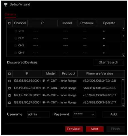
4.1 Channel
Channel settings configure the individual requirements for each Camera which include Encoding, Sensor Setting, OSD, Privacy Zone, ROI, Microphone, Human, Thermal and Smart Intelligent Tracking.
Camera: Cameras are added automatically by selecting “Click to Add” or manually by Selecting “Add”. Tick all appropriate Cameras to select them or select “Delete” to delete unwanted cameras. Cameras firmware can be bulk updated, please refer to the Gateway manual for further information.

4.2 Recording Settings
Recording settings allow for the configuration of Recording Schedules, HDD Storage Calculations, SMART Recording, HDD Detection Alert.
4.3 Alarm Notifications and Settings
Configure the Alarm Notifications for General Alarms, Motion Detection, Video Loss, AI Intelligent Anaytics, Abnormal Alarms and Alarm Outputs.

General Settings: Enable or Disable the alarm functions and set the duration time for the event.
Motion Detection: By enabling Motion Detection alarm conditions can be communicated or activated when triggered. The following can be configured.
- Event actions: Activate the Gateway Buzzer, trigger the alarm output, push notifications to the IR Connect Mobile App, activate alarms in the Inner Range controller, pop-up messages to the monitor, send E-mail and post event recording.
- Motion Detection Area: Activate the Gateway Buzzer, trigger the alarm output, push notifications to the IR Connect Mobile App, activate alarms in the Inner Range controller, pop-up messages to the monitor, send E-mail and post event recording.
- Motion Detection Schedule: Set the schedule to enable or disable Motion Detection Alarms. These can be defined as all day, specific daily periods or single one off periods.
Video Loss and Intelligent Analysis have the same configuration settings as Motion Detection.
Alarm In: Configure the settings for the Alarm Inputs alarm conditions.
Health Alerts: Select HDD error, IP conflict or network disconnected.
4.4 Network Settings
Network settings contain Network, 802.1X, DDNS, E-mail, Port Mapping, P2P, IP Filter, SNMP, 3G/4G, and PPPoE as shown in figure 4-3.

Network,802.1X, DDNS, and SNMP Settings: Interface to set network parameters.
E-mail: Set E-mail addresses for sending and receiving alarm messages as well as the password reset email address..
Port Mapping: Set the ports for remote accessing.
P2P: Add the Gateway into the device list of the IR Connect Mobile App by accessing the QR code.
IP Filter: Settings for creating black or white lists.
PPPoE: Point to point network to access NVR directly.
4.5 System Settings
System settings allows for the configuration of the following Gateway parameters: General, User, Security Center, Auto Sequence, Logs, Maintenance and Auto Restart, as shown in Figure 4-4.

General: Includes the configuration of the system, date and time, time zone, DST.
User: Add users and advanced settings (auto login, password double authentication, boot wizard).
Security Center: Modify the password, pattern unlock, secure Email, Secure question.
Auto Sequence: Settings for sequencing view of the Camera channels.
Logs: Shows the system events and alarm log that can be exported to USB.
Maintenance: Includes shutdown, reboot, exit system, reset, import configuration, export configuration and updates.
Auto Restart: enable this function to make device restart periodically.
4.6 Live Video
Live video page is displayed after starting the NVR by default, as shown in figure 4-5.

IR CONNECT Mobile App Setup
Install the IR CONNECT Mobile App available from Apple or Google.
Use the App to scan the QR code on the Rear Panel of the Gateway or from the setup screen in the P2P settings page of the Gateways user interface. Once connected, input the password of the NVR into the Gateway device list of the IR CONNECT Mobile App. Now the user has access through the Mobile Application.

Web Browser Access
The Gateway can be accessed via a Web browser. Enter the IP address of the device (The default IP address is 192.168.0.121) into the Web Browsers address box, and press Enter. The login page is displayed as shown in figure 6-1.

NOTE: The user name and password are same as the UI interface.
Network Setup / Device Activation
The camera can be either activated with your Inner Range Gateway (NVR) or directly from the built in web interface.
Activation with a Gateway
- Connect the Camera to one of the POE ports on the Gateway with a network cable.
- The Gateway will automatically discover and adopt the camera.
- Alternatively, you can connect the camera to the same network the Gateway is on and allow the Gateways built in search functionality to discover and adopt it. Please consult the Gateway documentation for further details.
Stand Alone Activation
- Connect the camera to your network, and power it (either by PoE or by the DC jack)
- Your camera is set to obtain an IP address automatically via DHCP.
- Discover the IP address that was assigned to your camera from either your network administration portal, or the “IR Video Search Tool” available in the downloads section of the Inner Range website (see QR Code on this guide).
Important Information
- Please read this guide thoroughly before using the device.
- Failure to use the product correctly may result in fire or injury.
- Improper use can lead to equipment damage, data loss, or poor performance.
Always follow the recommended guidelines for installation and usage. - Always use accessories provided with the camera. Ensure the voltage aligns with the device’s input requirements.
Installation and Usage Precautions
- Install according to the given guidelines to prevent damage.
- Use only power adapters compliant with local safety.
- If powered by PoE (power over ethernet ) ensure the powering device has sufficient PoE budget to allow all devices to operate at their maximum rated power (see datasheet ).

Quick Setup Guide – Copyright © Inner Range Pty Ltd October 2024
The specifications and descriptions of products and services contained in this document were correct at the time of release of this document. Inner Range Pty Ltd reserves the right to change specifications or withdraw products without notice.
This document cannot be re-published or re-hosted without the prior written consent of Inner Range. For the latest version of this document, please visit the Inner Range website.
Documents / Resources
 | inner range IR-V-N4C4T-110 IR Video Gateway [pdf] User Guide IR-V-N4C4T-110, IR-V-N4C4T-110 IR Video Gateway, IR Video Gateway, Video Gateway, Gateway |