IMMERGAS Modulating remote control 38

Instructions
- Attention should be paid to
- valid local regulations
- the statutory provisions for prevention of industrial accidents,
- the statutory provisions for environmental protection,
- the Health and Safety at Work Act 1974
- Part P of the Building Regulations 2005
- BS7671 Requirements for electrical installations and relevant safety regulations of DIN, EN, DVGW, TRGI, TRF and VDE.
- These instructions are exclusively addressed to authorised skilled personnel.
- Only qualified electricians should carry out installation and maintenance work.
- Initial installation should be carried out by named qualified personnel
- system-monitoring display
- up to 4 temperature sensors Pt1000
- heat quantity measurement
- function control
- user-friendly operation through simple handling
- solar operating hours counter and thermostat function

Scope of delivery
- 1 x Controller
- 1 x accessory bag
- 1 x fuse T4A
- 2 x screws and dowels
- 4 x strain relief and screws
- Additionally enclosed in the full kit:
- 1 x collector sensor FKP6
- 2 x boiler sensors FRP6

Technical data
Housing:
- plastic, PC-ABS and PMMA
- Protection type: IP 20 / DIN 40050
- Ambient temp.: 0 … 40 °C
- Dimensions: 172 x 110 x 47 mm
- Mounting: wall mounting, and mounting into patch panels is possible
- Display: System screen for systems visualization, 16-segment display, 7-segment display, 8 symbols for system status and operating control lamp
- Operation: 3 push buttons at the front of the housing
Functions:
Differential temperature controller with an optional system functions. Function control according to BAW guidelines, operating hours counter for the solar pump, tube collector function as well as heat quantity measurement.
- Inputs: for 4 temperature sensors Pt1000
- Outputs: 2 standard relay
- Power supply: 220 … 240 V~
- Mode of operation: Type 1.b
- Switching capacity: electromechanical relay: 2 (1) A (220 … 240) V~
Examples
Installation
- The unit must only be located in dry interior locations. It is not suitable for installation in hazardous locations and should not be placed close to any electromagnetic fields. The controller must additionally be supplied from a double-pole switch with contact gap of at least 3 mm. Please pay attention to separate routing of sensor cables and mains cables.
- Unscrew the cross-head screw from the cover and remove it along with the cover from the housing.
- Mark the upper fastening point on the wall and drill and fasten the enclosed wall plug and screw leaving the head protruding.
- Hang the housing from the upper fastening point and mark the lower fastening point through the hole in the terminal box (centres 130 mm). Drill and insert the lower wall plug.
- Fasten the housing to the wall with lower fastening screw and tighten
 .
.
Electrical connection
The power supply to the controller must be carried out via an external power switch (last step!) and the supply voltage must be 220 … 240 V~ (50 … 60 Hz). Flexible cables must be attached to the housing with the enclosed strain relief and the corresponding screws. The controller is equipped with 2 relays to which loads such as pumps, valves, etc. can be connected:
- Relay 1
- 18 = conductor R1
- 17 = neutral conductor N
- 13 = ground clamp
- Relay 2
- 16 = conductor R2
- 15 = neutral conductor N
- 14 = ground clamp
- Temperature sensors (S1 to S4) have to be connected to the following terminals (either polarity):
- 1 / 2 = sensor 1 (e.g. sensor collector 1)
- 3 / 4 = sensor 2 (e.g. sensor store 1)
- 5 / 6 = sensor 3 (e.g. store top sensor)
- 7 / 8 = sensor 4 (e.g. return temperature sensor)
- The power supply connection has to be carried out via the following terminals:
- 19 = neutral conductor N
- 20 = conductor L
- 12 = ground clamp
Allocation of terminals for system 1
Allocation of terminals for system 2
Operation and function
The controller is operated via the 3 push buttons below the display. The forward button (1) is used for scrolling forward through the display menu or to increase the adjustment values. The backward button (2) is similarly used for scrolling backwards and reducing values. In order to access the adjustment mode, scroll down in the diplay menu and press the forward button (1) for approx. 2 seconds after you have reached the last display item. If an
adjustment value is shown on the display, the „SEt“ icon is displayed. Now, you can access the adjustment mode by using button 3.
- Press buttons 1 and 2 in order to select a channel
- Briefly press button 3, „SEt“ will flash
- Adjust the value by pressing buttons 1 and 2
- Briefly press buttons 3, so that „SEt“ permanently appears, the adjusted value will be saved.
The system monitoring display consists of 3 blocks: channel display, tool bar and system screen (active arrangement). The channel display consists of two lines. The upper line is an alpha-numeric 16-segment display (text display) for
displaying channel names and menu items. In the lower 7-segment display, the channel values and the adjustment parameters are displayed. Temperatures and temperature differences are indicated in°C or K respectively. The additional symbols in the tool bar indicate the actual system status.
System monitoring display
Channel display
Tool bar
System screen
The system screen (active arrangement) shows the scheme which has been selected. The screen consists of several system component symbols, which are – depending on the current status of the system – either flashing, permanently shown or „hidden“.
Flashing codes
- Pump symbols are flashing during initialization phase
- Sensor symbols are flashing if the corresponding sensor display channel is selected.
- Sensor symbols are flashing in the case of a sensor fault.
- Burner symbol is flashing if the after-heating is active
LED flashing codes
- green: everything OK
- red/green flashing: initialization phase manual operation
- red flashing: sensor fault(sensor symbol is flashing quickly)
Commissioning
- Switch on power supply. During the initialisation phase, the operating control lamp flashes red and green. After initialisation, the controller is in the automatic mode with settings. The pre-programmed system scheme is Arr 1.
- select adjustment channel Arr
- change to the -mode (see 2.1)
- select the arrangement via the Arr-index number
- save the adjustment by pressing the button
Arr 1
Arr 2
Control parameters and display channels
Legend:
- Corresponding channel is available.
- Corresponding channel is available when the corresponding option is enabled
- Only if the option heat quantity measurement is activated (OHQM), will the corresponding channel be available
- Only if the option heat quantity measurement is deactivated (OHQM), will the corresponding channel be available
- Only if an antifreeze (MEDT) other than water or Tyfocor LS / G-LS (MEDT 0 or 3) is used, will the channel antifreeze concentration (MED%) be displayed.
channel
Arr description page 1 2* COL x x Temperature collector 1 11 TST x Temperature store 1 11 TSTL x Temperature store 1 base 11 TSTU x Temperature store 1 top 11 S3 x Temperature sensor 3 11 TRF Temperature return sensor 11 S4 Temperature sensor 4 11 h P x Operating hours relay 1 11 h P1 x Operating hours relay 1 11 h P2 x Operating hours relay 2 11 kWh Heat quantity kWh 12 MWh Heat quantity MWh 12 Arr 1-2 Arrangement 9 DT O x x Switch-on temperature difference 13 DT F x x Switch-off temperature difference 13 S MX x x Maximum temperature store 1 13 EM x x Emergency temperature collector 1 14 channel
Arr description page 1 2 OCX x x Option collector cooling collector 1 14 CMX x* x* Maximum temperature collector 1 14 OCN x x Option minimum limitation collector 1 14 CMN x* x* Minimun temperature collector 1 14 OCF x x Option antifreeze collector 1 14 CFR x* x* Antifreeze temperature collector 1 14 OREC x x Option recooling 15 O TC x x Option tube collector 15 AH O x Switch-on temp. for thermostat 1 15 AH F x Switch-off temp. for thermostat 1 15 OHQM x Option heat quentity measurement 12 FMAX Maximum flowrate 12 MEDT Antifreeze type 12 MED% MEDT MEDT Antifreeze concentration 12 HND1 x x Manual operation relay 1 16 HND2 x x Manual operation relay 2 16 LANG x x Language 16 PROG XX.XX Program number VERS X.XX Version number
TEMPERATURE
- Collector temperature

- Store temperatures

- Sensor 3 and sensor 4

- Other temperatures

Operating hours counter
2.1.1 h P / h P1 / h P2:
Heat quantity measurement option
- OHQM:Heat quantity measurement Adjustment range: OFF …ON Factory setting: OFF

- FMAX: Flow rate in l/min Adjustment range 0 … 20 in 0,1-steps Factory setting: 2,0

- MEDT: Antifreeze type Adjustment range: 0 …3 Factory setting: 1

- MED%: Antifreeze concen- tration (Vol-) % When water or ethylene glycol is used, the parameter MED% is ‚hidden‘. Adjustment range: 20 …70 Factory setting: 4

- kWh/MWh: Heat quantity in kWh / MWh Display channel
Operating hours counter Display channel
The operating hours counter accumulates the solar operating hours of the respective relay (h P / h P1 / hP2). Full hours are displayed. The accumulated operating hours can be set back to zero. As soon as one operating hours channel is selected, the symbol is displayed. Press the SET (3) button for approx. 2seconds in order to access the RESET mode of the counter. The display symbol will flash and the operating hours will be set to 0. Confirm the reset with the button in order to finish the reset.In order to interrupt the RESET process, do not press a button for about 5 seconds. The display returns to display mode.
Heat quantity measurement option
Heat quantity measurement is possible if a flowmeter is used. For this purpose, the heat quantity measurement option (OHQM) has to be enabled. The flow rate should be read from the flow meter (l/min)and has to be adjusted in the channel FMAX. Antifreeze type and concentration of the heat transfer medium have to be adjusted in the channels MEDT and MED%. The flow rate as well as the reference sensors S1 (flow) and S4 (return) are used for calculating the heat quantity supplied.It is shown in kWh in the channel kWh and in MWhin the channel MWh. The overall heat quantity results from the sum of both values.The accumulated heat quantity can be reset. As soon as one of the display channels of the heat quantity is selected, the symbol is permanently shown on the display. Press button SET (3) for about 2 seconds in order to access the RESET mode of the counter. The display symbol will flash and the heat quantity value will be set to 0. In order to finish this process, press the button to confirm. In order to interrupt the RESET process, no button should be pressed for about 5 seconds. The controller automatically returns to the display mode.
T-regulation
This function is a standard differential control. If the switch on the differential is reached (DT O), the pump is operated. The pump runs at 100% speed for 10 seconds. After this period, the pump runs at minimum pump speed (NMN = 30 %). If the temperature difference reaches the adjusted set value the pump speed will increase by 10 % respectively until the maximum pump speed of 100 % is reached. The response of the controller can be adapted via the parameter „Rise“.If the temperature difference falls below the adjusted switch-off temperature difference (DTF), the controller switches off. If the adjusted maximum temperature is exceeded, the store will no longer be loaded in order to avoid damage caused by overheating. If the maximum store temperature is exceeded, will be shown. Please note: The controller is equipped with a store emergency shutdown function, which prevents the store from being loaded when the store temperature exceeds 85 °C.
 Maximum store temperature
System cooling
When the adjusted maximum store temperature is reached, the system stagnates. If the collector temperature increase to the adjusted maximum collector temperature (CMX),the solar pump is activated until the collector temperature falls below the maximum collector temperature. The store temperature may increase (subordinate active maximum store temperature), but only up to 85 °C (emergency shutdown of the store). If the store temperatures higher than the maximum store temperature (S MX) and if the collector temperature is at least 5 K below the store temperature, the solar system remains activated until the store is cooled down below the adjusted maximum temperature (S MX) via the collector and the pipework.If the system cooling function is enabled, (flashing) is shown on the display. Due to the cooling function, the system will have a longer operation time on hot summer day and guarantees thermal relief of the collector field and the heat transfer fluid.

Minimum collector function
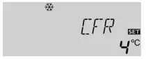
The minimum collector temperature is the minimum temperature that must be exceeded for the solar pump (R1) to switch on. The minimum temperature prevents the pump from being switched on too often at low collector temperatures. If the temperature falls below the minimum temperature, (flashing) is shown on the display. The antifreeze function activates the loading circuit between the collector and the store when the temperature falls below the adjusted antifreeze temperature. This will protect the fluid against freezing or coagulating. If the adjusted antifreeze temperature is exceeded by 1 °C, the loading circuit will be deactivated. Please note: Since this function uses the limited heat quantity of the store, the antifreeze function should be used in regions with few days of temperatures around the freezing point


Recooling function
If the adjusted maximum store temperature (S MX) is reached, the controller keeps the solar pump running in order to prevent the collector from being overheated. The store temperature may increase but only up to 85 °C (emergency shutdown of the store). The solar pump is switched on once the collector temperature is lower than the store temperature. It is switched off when the store is cooled down to the adjusted maximum temperature via the collector and the pipework.
Tube collector function
Thermostat function
The thermostat function works independently from the solar operation and can be used for using surplus energy or for after-heating.


Operating mode
For control and service work, the operating mode of the controller can be manually adjusted. For this purpose, select the adjustment value HND1 / HND2. The following adjustments can be carried out
Language
LANG: Language choice Adjustment range: dE, En, It, Fr Factory setting: It In this channel, different languages are available.
- dE : German
- En : English
- It : Italiano
- Fr : French

Troubleshooting

Various


Documents / Resources
 | IMMERGAS Modulating remote control [pdf] User Guide System MonitoringModulating remote control Display |


