ICP DAS GW-2492M BACnet IP Server to Modbus RTU Master Gateway User Manual
Important Information
Warranty
All products manufactured by ICP DAS are under warranty regarding defective materials for a period of one year, beginning from the date of delivery to the original purchaser.
Warning
ICP DAS assumes no liability for any damage resulting from the use of this product.ICP DAS reserves the right to change this manual at any time without notice. The information furnished by ICP DAS is believed to be accurate and reliable. However, no responsibility is assumed by ICP DAS for its use, not for any infringements of patents or other rights of third parties resulting from its use.
Copyright
Copyright @ 2021 by ICP DAS Co., Ltd. All rights are reserved.
Trademark
Names are used for identification purpose only and may be registered trademarks of their respective companies.
Contact us
If you encounter any problems while operating this device, feel free to contact us via mail at: service@icpdas.com.
General Information
BACnet/IP Protocol
BACnet is a communications protocol for building automation and control networks. It is an ASHRAE, ANSI, and ISO standard protocol. BACnet was designed to allow communication of building automation and control systems for applications such as heating, ventilating, and air-conditioning control, lighting control, access control, and fire detection systems and their associated equipment. The protocol provides mechanisms for computerized building automation devices to exchange information, regardless of the particular building service they perform. BACnet/IP is based on Ethernet and used UDP to transmit BACnet network packets (NPDU).
Messages are transmitted such as “Who-is” and “Who-has” through broadcast feature of UDP.
The feature allows that the user could search for device information without knowing the actual location of the device.
Modbus Protocol
Modbus protocol mainly has two versions RTU and TCP. RTU can be realized through COM interface and TCP can be realized through Ethernet. These two protocols are commonly used in industrial control and automation industry.
Modbus RTU is used to transmit and exchange data via RS-485. It’s a serial communication between master and slave. Every slave has a unique address to identify. Users could implement communication through using different function codes.
MODBUS TCP is a variant of MODBUS RTU. MODBUS messages are passed in an
“Intranet” or “Internet” environment by using the TCP/IP protocol. The most common use of this protocol is to connect PLCs and gateways to other simple fieldbus or I/O networks via Ethernet.
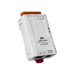
About GW-2492M
GW-2492M is a BACnet/IP Server to Modbus RTU Master Gateway. It allows BACnet client application to accesse Modbus RTU devices via GW-2492M module. The BACnet/IP protocol is used to relay and exchange information between building devices. GW-2492M contains a large number of BACnet objects (AI, AO, AV, BI, BO, BV, MSI, MSO, MSV) gives you flexibility in mapping Modbus RTU registers to any combination of BACnet objects. Multiple BIBBs (DS-RP-B, DS-RPM-B, DS-WP-B, DS-WPM-B,…etc.) are supported. All the data transfer is configurable using a standard web browser.
Features
- Read/Write Modbus registers via BACnet objects.
- Configurable BACnet/IP Server.
- Configurable Modbus RTU Master.
- Supports BACnet AI, AO, AV, BI, BO, BV, MSI, MSO, MSV Object Types
- Supports Modbus discrete inputs, coils, input registers and holding registers
- Supports up to 180 DI, 180 DO, 180 AI and 180 AO to transfer to BACnet Objects
- Simple data translation allows you to manipulate data as it passes between protocol

GW-2492M (BACnet/IP Server to Modbus RTU Master Gateway)
| Ethernet | |
| Controller | 10/100Base-TX Ethernet Controller (Auto-negotiating, Auto_MDIX) |
| Connector | RJ-45 with Ethernet indictor |
| Protocol | BACnet/IP Server |
| Max. Connections | 8 |
| BIBBS | DS-RP-B, DS-RPM-B, DS-WP-B, DS-WPM-B, DM-DDB-B, DM-DOB-B,DM-DCC-B, DM-RD-B |
| COM Interface | |
| Connector | Terminal block (RS485:D+, D- ; RS232:TXD, RXD, GND) |
| Baud Rate (bps) | 1200, 2400, 4800, 9600, 19200, 38400, 57600, 115200 |
| Comm. format | N81, N82, O71, O81, E71, E81 |
| Terminator Resistor | Built-in 120 ohm terminator resistor, enabled/disabled via Jump |
| Isolation | 3 kV VDC for DC to DC, 2500 Vrms for photo couple |
| Protocol | BACnet RTU Master |
| Maximum Slaves | 32 |
| Power | |
| Protection | Power reverse polarity protection |
| EMS Protection | ESD, Surge, EFT |
| Supply Voltage | +10 VDC ~ +30 VDC |
| Consumption | 5 W @ 24 VDC |
| LED Indicator | |
| LED (Round) | Power (1), BACnet MS/TP Status (1), BACnet MS/TP Net(1),Modbus TCP TxD / RxD / Link (3) |
| Ethernet LED | Ethernet LED Ethernet Status (RJ-45) (2) |
| Mechanism | |
| Installation | DIN-Rail |
| Casing | Metal |
| Dimensions | 33 x 120 x 116 mm (W x L x H) |
| Environment | |
| Operating Temp. | -25℃ ~ +75℃ |
| Storage Temp. | -30℃ ~ +85℃ |
| Humidity | 10 ~ 90% RH, non-condensing |
Hardware
Size (Unit : mm)

Appearance
The GW-2492M is equipped with a RJ45 port for Ethernet LAN connection. When 100BASE‐TX is operating, the 10/100M LED is lit orange. When an Ethernet link is detected and an Ethernet packet is received, the Link/Act LED is lit green.

LED Indicator
There are six LEDs to indicate the various states of the GW-2492M. The following is the illustration of these six LEDs.
Figure 2.1 LED position of the GW-2492M
| LED Name | GW-2492M Status | LED Status |
| ALL LEDs | FW Updating Mode | LED will be twinkledsequentially. |
| FW Initial Mode | LED will be twinkled per500ms. | |
| PWR(Module) | Power On | On |
| Power Failure | Off | |
| NET(BACnet/IP) | Connected by least one client | On |
| No clients connect | Blink per 200 ms | |
| STA(BACnet/IP) | Communication OK | On |
| Communication Failure | Blink per 200 ms | |
| CNT(Modbus) | Connect to least one device | On |
| No devices are connected | Blink per 200 ms | |
| RxD(Modbus) | Data reception | On |
| No Data reception | Off | |
| TxD (Modbus) | Data transmission | On |
| No Data reception | Off |
Getting Started With GW-2492M
This chapter mainly describes the operation process of the GW-2492M.
Wiring Preparation
Before setting up the GW-2492M, please complete the necessary preparation about wiring.
Please follow Figure 2.1 wiring diagram, to wire the following items:
- Power Supply : +10 VDC ~ +30 VDC
- RS-485:D+ & D- (for GW-2492M’s serial communication)
- Ethernet:Connect the GW-2492M and computer into the same LAN through cable or Ethernet Switch/Hub.
- INIT:Connect to GND to initial mode. (Address IP:192.168.255.1)
- FW:Connect to GND and insert RJ45 to download mode. (LED will be twinkled.)

Figure 3.1 GW-2492M Wiring Diagram
GW-2492M Web Configuration
Please follow those steps to configure the GW-2492M via web browser.
Step0:
Use the default account “admin” and the password “admin” to enter the main setting page.

Step1:
The firmware version is shown on the web.
Step2:
The GW-2492M is based on the information security law. Users need to change account or password for the first time before using it.
Step3:
Please relish the web page and login again with new account and password. “Module Setting” page will appear. Users could set the IP of the module.
Step4:
Press “Serial Port” to modify the parameters of the Modbus.
Step5-1:
Press “Modify” to configure the parameters of Modbus in the Modbus page.
Step5-2:
- Press “+” button to add a Modbus RTU node.
- After editing “Modbus Name” and “Address”, press “+” button to add Modbus registers.
- Press “+” button to add Modbus function codes and registers range.
- Finally, the users need to press “save” to save all Modbus configuration into GW-2492M.
- The users need to restart GW-2492M to make configuration work

- Press the icon to edit a Modbus registers of that node
- Press the icon to delete that Modbus node.

Step6:
Press “+” button to add a BACnet object.
- The “Object” field is BACnet object which support AI/AO/AV/BI/BO/BV/MI/MO/MV.
- The “No” field is the serial number of the BACnet object. If you have AI*3 and AO*4, you need assign the No as AI-0, AI-1, AI-2, AO-0, AO-1, AO-2, AO-3.
- The “Type” field is the Modbus register type. The common configuration is shown below.
- BACnet BO object maps to Modbus Coil Output(0x)
- BACnet BI object maps to Modbus Input Status(1x)
- BACnet AO object maps to Modbus Holding Register(4x)
- BACnet AI object maps to Modbus Input Register(3x)
- The “Address” field is the start address of the Integrated Modbus Register (Note1).
- The “Format” field is the data format which support bool/int16/uint16/int32/uint32/float.
- The “Index” field is reserved.
- The “Range” field is the exact Modbus address of the register.

Note 1.
In the GW-2492M, all remote Modbus data which come from different remote Modbus RTU devices will be integrated by their register type. It means that all remote Coil Output data will be putted into a Coil Output integrated buffer. All remote Input Status data will be putted into an Input Status integrated buffer. There are also have Holding Register integrated buffer and Input Register integrated buffer in the GW-2492M. They ware integrated as the illustration shown below.
The BACnet object will read or wirte the data from those integrated buffers. Those Modbus data with the same type will be ordered by the Modbus Configuration Index in the integrated buffer. The first configuration Modbus command will be in the first address of the buffer. The order was shown below.
For example by the illustration in Holding Register(4x), the Device4 and command 1 is the first configuration item of all Holding Register(4x). The Device4 and command 1 occupies the first address of the Holding Register buffer. The “Address” field of the BACnet object means that the address in those integrated buffers. For example by the illustration, if the address of the BACnet “BO” object is 11, it means that the data of the “BO” object comes from the second bit of the
Device 1 and command 2 in the Coil Output buffer. If the address of the BACnet “AO” object(int16) is 7, it means that the output data of the “AO” object(int16) will be written to the 8-th words of Device 4 and command 1 in the Holding Register buffer.
Import/Export Configuration
Export All Configurations to CSV file:
The GW-2492M supports export function to write all configurations into a csv file.
Import All Configurations from CSV file :
The users could import all configurations from a CSV file. It is convinient to move all configurations from one GW-2492M to another one. Firstly, the users select the CSV file. And then, they can press “Import” button to import configurations into the GW-2492M modules.
How to restore default Account/Password
If the users have forgotten the login information, they can follow the steps to restore default login information.
- Short the “INIT” and “GND” pin of GW-2492M and turn on the power.
- The GW-2492M will restore the login information.
- IP : 192.168.255.1
- Mask : 255. 255. 0 .0
- Gateway: 192.168.0.1
- Login Account: admin
- Login Password: admin

How to update the firmware
The GW-2492M can update the firmware via a software tool (Windows) by the following:
- Download the latest version of the firmware program and update Tool (FW_Update_Tool) on the website of the GW-2492M and store it in a computer that you want to connect to GW-2492M.
Update Tool: Please refers to ->
https://www.icpdas.com/en/download/show.php?num=7823&model=GW-2492M - Short the “FW” and “GND” pin of the GW-2492M and turn on the power. When the six LEDs of the GW-2492M turn blinking alternately, the GW-2492M is successfully entered the firmware updating mode.

Figure 3.2 GW-2492M FW & GND Pin
Execute “FW_Update_Tool.exe” with the administrator privileges ( ) and follow the steps as
Figure 3.3:
- In “Download Interface”, select a network port for connecting to GW-2492M
- In “Firmware Path”, select the latest firmware update file (GW_2492M_xxxx.fw).
- In “Firmware Update”, click “Update” to start the firmware updating.
When the update is completed, “Update OK” will be displayed in the “FW_Update_Tool” window to indicate that the firmware updating is successful. Next, remove the short connection between FW and GND, and reboot the power supply, then check the current firmware version on the Web interface.

Figure 3.3 FW_Update_Tool firmware update steps
GW-2492M (BACnet/IP Server to Modbus RTU Master Gateway) User Manual Ver 1.10
Copyright © 2021 ICP DAS Co., Ltd. All Rights Reserved E-mail: service@icpdas.com

Documents / Resources
 | ICP DAS GW-2492M BACnet IP Server to Modbus RTU Master Gateway [pdf] User Manual GW-2139M CR, GW-2492M, GW-2492M BACnet IP Server to Modbus RTU Master Gateway, BACnet IP Server to Modbus RTU Master Gateway, IP Server to Modbus RTU Master Gateway, Server to Modbus RTU Master Gateway, Modbus RTU Master Gateway, RTU Master Gateway, Master Gateway, Gateway |