GARMIN LC102, LC302 Spectra LED Control Module

Specifications
- Product Name: Garmin Spectra LED Control Module
- Model: GUID-6A3E1D9B-1E17-4069-BF5C-3C82F2202A9B v3
- Release Date: May 2025
Product Usage Instructions
- Select a suitable location based on mounting considerations.
- Mark pilot hole locations on the mounting surface.
- Drill pilot holes using a 2 mm (3/32 in.) drill bit.
- Fasten pan-head screws into the pilot holes.
- Secure the device by tightening the screws without overtightening to avoid damage.
- Prioritize planning the layout of the device, power wiring, NMEA 2000 network, and LED lighting devices before making any connections.
- Refer to specific connection sections for detailed information.
Important Safety Information
WARNING
- See the Important Safety and Product Information guide in the product box for product warnings and other important information.
- Failure to install this device according to these instructions could result in personal injury, damage to the vessel or device, or poor product performance.
- To avoid possible personal injury or damage to the device and vessel, disconnect the vessel’s power supply before beginning to install the device.
CAUTION
- To avoid possible personal injury, always wear safety goggles, ear protection, and a dust mask when drilling, cutting, or sanding.
NOTICE
- To avoid damage to your boat, this device should be installed by a qualified marine installer. Specific knowledge of marine electrical systems is required for proper installation.
- When drilling or cutting, always check what is on the opposite side of the surface to avoid damaging the vessel.
- If you are mounting the device in fiberglass, when drilling the pilot holes, use a countersink bit to drill a clearance counterbore through only the top gel-coat layer. This will help prevent cracking in the gelcoat layer when the screws are tightened.
Tools and Supplies Needed
- 16 AWG (1.3 mm2) wire to connect the wiring harness to power
- Inline fuse appropriately rated for the power source, and connected LEDs (Connecting to Power, page 4).
- 20 AWG (0.5 mm2) wire to connect the wiring harness to lighting You can purchase marine LED cable from your Fusion® or Garmin® dealer in 100m (328 ft.) lengths (010-13386-00).
- #2 Phillips screwdriver
- Appropriately sized marine-grade connectors for connecting the wiring harnesses to the speaker wire
- Wire cutters
- Drill and 2 mm (3/32 in.) drill bit for mounting the LED control module
Getting Started
- The Garmin Spectra LED control module allows you to control connected LED lights using compatible Garmin chartplotters and compatible Fusion stereos connected to the same NMEA 2000® network. You can also control connected LED lights using the ActiveCaptain® app.
- The Garmin Spectra LED control module is designed for controlling only LED lighting. You must not use this device to control navigation lights, non-LED lighting, or other devices.
- This manual contains instructions for installing and performing the initial configuration for the Garmin Spectra LED control module using a Garmin chartplotter or the ActiveCaptain app.
- For complete instructions on using the Garmin Spectra LED control module with a connected chartplotter or Fusion stereo, see the latest chartplotter or stereo owner’s manual.
Downloading the Latest Chartplotter or Stereo Owner’s Manual
For complete operating and customization instructions for the LED lighting features, download the latest version of the owner’s manual for your chartplotter or stereo from the Garmin website.
- Go to garmin.com/manuals/ or scan this QR code.
- Enter the name of your chartplotter or stereo and select the appropriate model from the results.
- Select Owner’s Manual on the manuals page.

Mounting Considerations
Selecting the correct mounting location is critical to optimizing the performance of the Garmin Spectra LED control module. When selecting a mounting location, observe these considerations.
- You should mount the device in an accessible location.
- You should not mount the device near fuel tanks or bilge areas where combustible fumes may accumulate.
- You should mount the device in a location with access to a common ground for other electronics.
- When controlling LED speakers, the controller should be mounted within 5 M (16 ft. 4 in.) of the speakers.
- You must mount the device in a location where it is not submerged.
- You should mount the device on a flat, vertical mounting surface, with the wire harness connectors pointing down.
- You should clear the mounting surface of dirt, debris, wax, or coatings.
- You should select a location away from sources that can interfere with the device’s operation. Sources of interference may include strong electromagnetic fields, such as power cables and electric motors.
Mounting the Device
Before you can mount the device, you must select a location in accordance with the mounting considerations. You must use the included mounting screws or acquire pan-head screws of the appropriate length for the mounting surface.
NOTICE
Do not use the Garmin Spectra LED control module as a template when drilling the mounting holes. Drilling through the mounting holes may damage the device and void the warranty.Do not apply grease or lubricant to the screws when fastening the device to the mounting surface. Grease or other lubricants can cause damage to the device housing.
You must use pan-head screws to secure the device. Using countersunk screws can damage the device housing.
- With the wiring-harness connectors pointing down, hold the device on a flat, vertical mounting surface and mark the locations for the pilot holes.
- Remove the device from the mounting surface.
- Using a 2 mm (3/32 in.) drill bit, drill the pilot holes.
- Fasten the included pan-head screws into the pilot holes.
- Secure the device to the mounting surface by tightening the screws until they are snug.
NOTICE
Do not overtighten the screws because it may damage the device housing.
Connection Considerations
You should carefully plan the layout of the device, the power wiring, the NMEA 2000 network, and all LED lighting devices before making any connections. This is a connection overview. See the relevant connection sections for more information on particular connections.
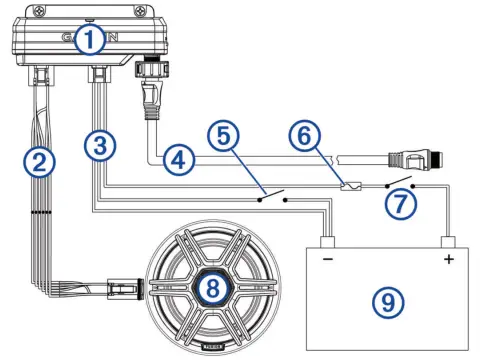
| 1 | Garmin Spectra LED Control Module |
| 2 | LED wiring harness |
| 3 | Power wiring harness |
| 4 | NMEA 2000 cable |
| 5 | Momentary switch (optional) |
| 6 | Appropriately rated slow-blow fuse (not included) |
| 7 | Ignition or ACC switch (recommended) |
| 8 | 12 or 24 Vdc LED lighting (LED speaker in this example) |
| 9 | 12 or 24 Vdc power source |
When making connections, observe these considerations.
- This device supports a maximum of 2 A per LED wiring harness. When planning lighting connections, consider the power needs of all potential load combinations to ensure that the total active load does not exceed 2 A per LED wiring harness when in use.
- You must connect all lighting to a common ground.
- You must make all bare wire connections using appropriately sized marine-grade, waterproof connectors or waterproof heat-shrink.
- You must insulate any unused bare wire connections after completing the installation.
- When extending wires, you must use the appropriate wire gauge for the individual wires on the wiring harnesses.
- To avoid interference, avoid bundling or routing speaker and LED wires together.
- This device must connect to the same NMEA 2000 network as the chartplotter or stereo you want to use for controlling the LED lighting (NMEA 2000 Network Connection).
Connecting to Power
WARNING
The wiring (not included) from the power source to the positive wire of the power wiring harness must run through a circuit breaker or in-line fuse (not included) as close to the power source as possible. See the ABYC or your local and regional standards for the required fuse or breaker rating. Connecting the device to power without a circuit breaker or in-line fuse may cause a fire if there is a short in the cable, resulting in property damage and/or serious personal injury.
NOTICE
The power supply voltage to the LED control module must match the voltage of the LED lighting it is controlling. Mixing 12 Vdc and 24 Vdc devices may damage your LED lighting.
- Route 16 AWG marine-grade, fully-tinned copper wire (not included) to the wiring harness and the common ground location on the boat, and select an option:
- Install a properly rated in-line fuse on the red power wire as close to the power source as possible.
- Identify or install a properly rated circuit breaker, as close to the power source as possible, for use with the power wire.
- Install marine-grade connectors or solder and heat shrink tubing on both the red power and black ground wires.
- NOTE: The pink and black wire is for an optional toggle switch, and must not be connected to the ignition (Connecting an Optional Momentary Switch).
- Connect the power plug.
Power Cable Extensions
If necessary, you can extend the power cable using 16 AWG (1.3 mm2) wire, The maximum length of the extension depends on the power source. Use marine-grade connectors or solder and water-resistant heat-shrink tubing when extending the power wires.
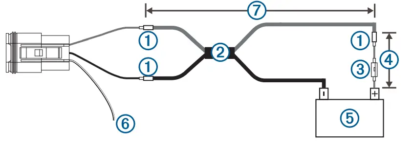
| 1 | Splice |
| 2 | 16 AWG (1.3 mm2) extension wires |
| 3 | Fuse (not included) |
| 4 | 20.3 cm (8 in.) minimum cable and fuse length before splice |
| 5 | 12 or 24 V power source |
| 6 | The pink and black wire is for an optional toggle switch, and must not be connected to the ignition (Connecting an Optional Momentary Switch) |
| 7 | Maximum extension (Maximum Power Cable Extension) |
Maximum Power Cable Extension
To find the maximum extension length you can use, cross-reference the voltage of your power supply with your LED control module. All extensions should be made using 16 AWG (1.3 mm2) marine-grade wire.
| Garmin Spectra Model | 12 Vdc Power Source | 24 Vdc Power Source |
| LC102 | Up to 7.5 m (24 ft. 7 in.) | Up to 15 m (49 ft. 2 in.) |
| LC302 | Up to 2.5 m (8 ft. 2 in.) | Up to 5 m (16 ft. 5 in.) |
Connecting an Optional Momentary Switch
You can connect an optional, normally open momentary switch to the Garmin Spectra LED Control Module to toggle all connected LED lights on and off without using a connected chartplotter, stereo, or app. When toggling lights on, the LEDs will restore the last-used lighting configuration.
- Connect the pink and black wire on the power wiring harness to the same ground connection as the negative wire through a normally open momentary switch (not included).
- If necessary, mount or install the switch according to the instructions provided with the switch.
- Connect the power wiring harness to the LED control module.
Connecting LED Wiring to the Wiring Harnesses
You must use the provided wiring harnesses to connect LED lights to the LED control module. The extension wire needed to connect the LED lights to the wiring harnesses is not included, but you can purchase marine LED cable (010-13386-00) from garmin.com or your Garmin dealer.
WARNING
In order to avoid accidental short circuits, disconnect the power supply to the Garmin Spectra LED control module before making any connections. Failure to disconnect the power supply could result in serious bodily injury, and/or damage to the device and/or vessel.
- Route appropriately gauged marine-grade, fully-tinned copper wire (not included) from the location of the device to the LED lights.
NOTE: You should label both ends of the wire so you can easily identify which wires route to which LEDs. - Connect the wire to the LEDs according to the documentation provided with the LED lights.
- Referring to this table, connect the wire to the wiring harnesses using appropriately gauged marine-grade connectors or solder, and waterproof heat shrink tubing.
| Wire Color | Wire Use |
| Dark blue | LED power (+VE) |
| Black/light green | Cool white LED (-VE) |
| Black/red | Red LED (-VE) |
| Black/green | Green LED (-VE) |
| Black/light blue | Blue LED (-VE) |
| Black/yellow | Warm white LED (-VE) |
- Connect the wiring harnesses to the ports on the Garmin Spectra LED control module.
NMEA 2000 Network Connection
- This diagram shows a sample installation which you can scale to apply to the NMEA 2000 network on your vessel. The device must receive power from a dedicated power connection and does not receive power from the NMEA 2000 network (Connecting to Power)
- If you are unfamiliar with the needs of a NMEA 2000 network, you should read the “NMEA 2000 Network Fundamentals” chapter of the Technical Reference for NMEA 2000 Products. To download the reference, go to garmin.com/manuals/nmea_2000
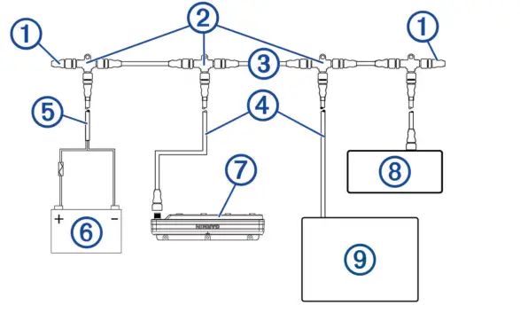
| Item | Description | Notes |
| 1 | NMEA 2000 terminator | NMEA 2000 terminators must connect to each end of the NMEA 2000 backbone. |
| 2 | NMEA 2000 T-connector | NMEA 2000 T-connectors must connect to one another using the sides of each T, and they must connect to NMEA 2000 devices using drop cables connected to the top of each T. |
| 3 | NMEA 2000 Backbone | |
| 4 | NMEA 2000 drop cable | A NMEA 2000 drop cable connects a device to the NMEA 2000 network. A NMEA 2000 drop cable should not exceed 6 m (20 ft.). |
| 5 | NMEA 2000 power cable | |
|
6 |
12 V power source | NOTICE If you are using a Garmin Spectra LED control module with a 24 Vdc power source and LEDs, you must not connect the NMEA 2000 network to the 24 Vdc source. Connecting the NMEA 2000 network to a power source greater than 12 Vdc will damage connected devices. |
| NOTE: The NMEA 2000 network and all LED control modules should connect to the same ground location. | ||
| 7 | Garmin Spectra LED control module | The Garmin Spectra LED control module must connect to the NMEA 2000 network, to a power source, and to lighting devices to function correctly. |
| 8 | Fusion stereo (optional) | The Fusion stereo must have a power connection separate from the NMEA 2000 network. |
| 9 | Garmin chartplotter | The Garmin chartplotter must have a power connection separate from the NMEA 2000 network. |
Configuration
Before you can use lights connected to the Garmin Spectra LED control module, you must first configure each light using a Garmin chartplotter or through the ActiveCaptain app. Once configured, the LED lighting connected to the LED control module can be controlled through a compatible Garmin chartplotter or Fusion stereo connected to the same NMEA 2000 network as the LED control module.
NOTICE
Using certain LED colors, such as red and green, may violate the laws, regulations, and standards related to the use and/or operation of marine navigation lights. It is the user’s responsibility to comply with any such applicable laws, regulations, and standards. Garmin is not responsible for any fines, penalties, citations, or damages that may be incurred due to any such lack of compliance.
- NOTE: If you have multiple chartplotters connected through a Garmin BlueNet™ network or Garmin Marine Network, each chartplotter must be connected to the same NMEA 2000 network as the Garmin Spectra LED control module to access the lighting
- controls.
- NOTE: If you have multiple stereos connected through a Fusion PartyBus™ network, each stereo must be connected to the same NMEA 2000 network as the Garmin Spectra LED control module to access lighting controls.
- NOTE: If you have both chartplotters and stereos installed on the vessel, you must connect them all to the same Garmin BlueNet network or Garmin Marine Network and to the same NMEA 2000 network as the Garmin Spectra LED control module to
- Synchronize lighting settings and behavior among all connected devices.
You can also configure LED lighting names, effects, and brightness levels. See the owner’s manual for your chartplotter or stereo for complete operational and configuration instructions.
Initializing Connected LED Lights Using a Chartplotter. Before you can interact with any connected LED lights using the chartplotter or stereo, you must first initialize the lights by providing information about the type of light source supported by the connected LEDs.
- From the lighting control screen on a compatible chartplotter connected to the same NMEA 2000 network as the Garmin Spectra LED control module, select Options > Installation > Lights.A list of all available lights is shown. Any light indicated with a yellow circle and Not Used as the Light Output must be initialized before it’s available for use by the system.
- Select a light from the list on the left.
- Select Light Output and select the type of LEDs connected:
- RGB: The connected dimmable LEDs support a full range of colors.
- RGBW: The connected dimmable LEDs support a full range of colors and high-quality white light.
- CRGBW: The connected dimmable LEDs support a full range of colors and multiple temperature white light.
- Single Channel: The dimmable LEDs support one dedicated color.
- TIP: You can select Identify to illuminate the selected light to help identify and test the selected LED type.Q
- Repeat this procedure for all connected lights until all of the intended LED lights are initialized.
LED Light Configuration for a Fusion Stereo Using the ActiveCaptain App
You can connect your mobile device to a compatible Fusion stereo using the ActiveCaptain app to configure and control lights connected to a Garmin Spectra LED control module. If the stereo and LED control module are connected to the same NMEA 2000 network as a compatible chartplotter, you should connect the ActiveCaptain app to the chartplotter instead of the stereo so you can use the full features included in the app in addition to the lighting controls. See the owner’s manual for the chartplotter for instructions.
NOTE: Before you can connect your mobile device to the stereo, you must either configure the stereo to act as a wireless access point or connect the stereo to a wireless router using an Ethernet cable.
Getting Started with the ActiveCaptain App
You can connect a mobile device to a compatible Fusion stereo using the ActiveCaptain app. The app provides a quick and easy way for you to configure and interact with the lights connected to a Garmin Spectra LED control module.
- If necessary, set up the stereo as a Wi‑Fi® access point or connect the stereo to a wireless router using an
Ethernet cable. - From the application store on your mobile device, install and open the ActiveCaptain app.
TIP: You can scan this QR code using your mobile device to download the app. - Log into the ActiveCaptain app using your Garmin account.

- Bring the mobile device within 32 m (105 ft.) of the stereo or the wireless router.
- In the ActiveCaptain app, select Connect.
- Select the SSID of the stereo or wireless router and provide the password, if necessary.
The app connects to the wireless network and returns to the main screen. After the app connects to the wireless router or stereo correctly, an option for Lighting is shown on the Boat Apps tab.
Initializing Connected LED Lights Using the ActiveCaptain App
Before you can interact with any connected LED lights using the stereo, you must first initialize the lights by providing information about the type of light source supported by the connected LEDs.
- If necessary, open the ActiveCaptain app and connect it to the stereo or wireless router.
- In the ActiveCaptain app, select Settings > Lighting. A list of connected LED control modules is shown.
- Select an LED control module with connected LED lights that you want to initialize and select Lights. A list of all available lights is shown. Any light indicated with a yellow circle must be initialized before it’s available for use by the system.
- Select a connected LED light from the list.
- Select Light Types and select the type of LEDs connected:
- RGB: The connected dimmable LEDs support a full range of colors.
- RGBW: The connected dimmable LEDs support a full range of colors and high quality white light.
- CRGBW: The connected dimmable LEDs support a full range of colors and multiple temperature white light.
- Single Channel: The dimmable LEDs support one dedicated color.
TIP: You can select Identify to illuminate the selected light to help identify and test the selected LED type.
- Repeat this procedure for all connected lights until all of the intended LED lights are initialized.
FAQ
- Q: Where can I find the latest owner’s manual for my chartplotter or stereo?
- A: You can download the latest owner’s manual from the Garmin website by visiting garmin.com/manuals/ or scanning the provided QR code. Enter your device’s name and model to access the appropriate manual.
- Q: What precautions should I take during installation?
- A: Always wear safety goggles, ear protection, and a dust mask when drilling, cutting, or sanding to prevent personal injury.Disconnect the vessel’s power supply before starting the installation to avoid accidents.
Documents / Resources
 | GARMIN LC102, LC302 Spectra LED Control Module [pdf] Installation Guide LC102 LC302 Spectra LED Control Module, LC102 LC302, Spectra LED Control Module, LED Control Module, Control Module, Module |