FW MURPHY MX4 Series Interchange Comm Control

Product Information: InterchangeTM Comm Control Module, MX4 Series
The MX4 expansion module is designed to provide temperature and frequency input capability to existing and future FW Murphy Controllers using CANbus proprietary communications. It also offers Modbus RTU RS485/RS232 for other communication requirements. The MX-Series modules can be added to enable Digital and Analog I/O and Thermocouple functionality for communication and monitoring by the master controller. The MX4 module is CSA C/US Listed, Class I, Div. 2 Groups B, C & D.
Product Dimensions and Mounting
The MX4 expansion module requires the MX4 Plug Kit (00030867) for installation.
Specifications
The MX4 module can read up to 18 thermocouples and 1 MPU.
Installation Instructions
When installing an MX4 Expansion I/O Module, power, I/O (Thermocouples and MPU), and communication wiring must be in accordance with Class 1, Division 2 wiring methods [Article 501-4(b) of the National Electrical Code, NFPA 70] and in accordance with the authority having jurisdiction.
MX4 Jumper Configuration
CANbus: Communication Link to Main I/O Module
LK1: This jumper provides a termination resistor for the CAN communication chain. This jumper should only be in place when the I/O module is the last in the communication chain. The MX4 cover needs to be removed to access this jumper link (LK1).
RS485 Communication Port: Slave Comm. Port
LK2: These jumpers provide a termination, pick-up, and pull-down resistors for the RS485 communication chain. The PU/PD jumpers should only be in one place on the communication chain. The TR jumper must be in place only when the I/O module is the last in the communication chain. The MX4 cover needs to be removed to access this jumper link (LK2).
Communication Address Select Shunts: Comm Address
(Note: The manual does not provide further information on this section)
Please refer to the installation manual for detailed instructions and diagrams.
Please read the following information before installing.
BEFORE BEGINNING INSTALLATION OF THIS FW MURPHY PRODUCT, READ AND FOLLOW ALL INSTALLATION INSTRUCTIONS.
EXPLOSION HAZARD: SUBSTITUTION OF COMPONENTS MAY IMPAIR SUITABILITY FOR CLASS 1, DIVISION 2.
EXPLOSION HAZARD: WHEN IN HAZARDOUS LOCATIONS, TURN OFF POWER BEFORE REPLACING OR WIRING MODULES.
EXPLOSION HAZARD: DO NOT DISCONNECT EQUIPMENT UNLESS POWER HAS BEEN SWITCHED OFF OR THE AREA IS KNOWN TO BE NON-HAZARDOUS.
Please contact FW Murphy Production Controls immediately if you have any questions.
FW Murphy Interchange Comm Control Module Series
The MX4 expansion module provides temperature and frequency input capability to existing and future FW Murphy Controllers using CANbus proprietary communications. Modbus RTU RS485/RS232 is also provided for other communication requirements. Any mix of MX-Series modules can be added to enable Digital and Analog I/O and Thermocouple functionality for communication and monitoring by the master controller.
MX4 Thermocouple / MPU
CSA C/US Listed, Class I, Div. 2 Groups B, C & D
The MX4 module adds thermocouple input ability to the master. It can read up to 18 thermocouples and 1 mpu.
Product Dimensions and Mounting

Accessories
MX4 Plug Kit (00030867) Printed Terminal Plugs for MX4 Expansion I/O Module
Specifications
- Operating Temperature: -40 to +85C (185°F)
- Storage Temperature: -40 to +85C (185°F)
- Power Input Voltage: 10 to 32 VDC (30W max)
MX4 Installation Instructions
When installing an MX4 Expansion I/O Module, power, I/O (Thermocouples and MPU) and communication wiring must be in accordance with Class 1, Division 2 wiring methods [Article 501-4(b) of the National Electrical Code, NFPA 70] and in accordance with the authority having jurisdiction.
Installation Diagram


MX4 Jumper Configuration
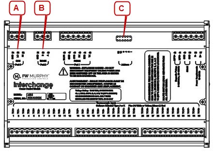
| A | CANbus: Communication Link to Main I/O Module LK1: This jumper provides a termination resistor for the CAN communication chain. This jumper must be in place only when the I/O module is the last in the communication chain. See control panel drawings for designation. The cover of the MX4 must be removed to access this jumper link (LK1). (Refer to the Communications chapter in this document)
|
| B | RS485 Communication Port: Slave Comm. Port. (See Pictorial Above) LK2: These jumpers provide a termination, pick-up and pull-down resistors for RS485 communication chain. The PU/PD jumpers should only be in one place on the communication chain. The TR jumper must be in place only when the I/O module is the last in the communication chain. See control panel drawings for designation. The cover of the MX4 must be removed to access this jumper link (LK2). (Refer to the Communications chapter in this document) |
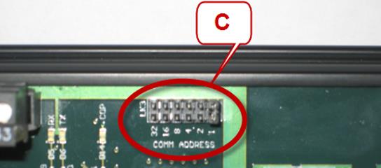
| C | Communication Address Select Shunts: Comm Address LK3: These jumpers allow you to assign a unique address to each MX4 that may be in the system. This allows the master controller to differentiate between the modules. For example, to name the controller address 5, place the shunts on LK1 and LK4. (Refer to the Communications chapter in this document)
|

Communications
Physical Layer: The MX4 module features one asynchronous RS232 serial communication port, one asynchronous RS485 serial communication port and one CANbus 2.0B proprietary communication port.
RS232 Interconnect: The module is equipped with screw terminals called Port 1. This connection is typically used to poll the information for a specific module using twisted shielded pair cable suitable for RS232 networks. The simplest form of these networks are 3-wire, half-duplex, using RX, TX and GND terminals. The TX terminal is the TRANSMIT DATA signal; the RX terminal is the RECEIVE DATA signal; and the GND is the COMMON GROUND signal for the communication line. These signal lines will take turns transmitting and receiving depending on the device using the RS232 network at any given instant. The MX4 also provides connections for CTS and DTR signals if required for 5 wire RS232 connections.
RS485 Interconnect: The module is equipped with screw terminals called Port 2. This connection is typically used to poll the information for a specific module using twisted shielded pair cable with 120 ohm impedance suitable for RS485 networks. These networks are 2-wire, half-duplex and feature an A terminal 49, B terminal 50 and SHD shielded ground connection. The A terminal is the + or non-inverting signal, and the B terminal is the – or inverting signal. These signal lines will take turns transmitting and receiving depending on the device using the RS485 network at any given instant.
Baud Rate: 9600 fixed (RS232/RS485)
Protocol: Modbus RTU. This is a binary communication protocol. All data will be contained in unsigned 16-bit Modbus Holding Registers (addressed starting at 40001). Following the Modbus RTU specification, the Most Significant Byte in a 16-bit word is broadcast first followed by the Least Significant Byte.
Refer to the Modbus RTU map provided in this manual for a detailed mapping of the available data and data scaling.
CANbus 2.0 B Interconnect: The module is equipped with screw terminals called Port 3. This connection is typically used to provide the interconnections between the main control module which polls the information for a specific module using twisted shielded pair cable with 120 ohm impedance suitable for CAN networks. This network protocol is proprietary CANbus and features a HI (CAN H) terminal 52, LO (CAN L) terminal 53 connection and SHD shielded ground connection.
Communication Address Select Shunts: A jumper shunt header is provided to assign a unique Modbus RTU and/or CANbus address to each expansion module that may be in the network. This allows the master controller to differentiate between the modules. Addressing is done in binary format, and each incrementing jumper increases the weight by a factor of 2.
For example, to name the controller address 5, place the shunts on LK1 and LK4. The sum makes 5 (4+1).
NOTE: RS485/RS232 Communication is 9600-N-8-1 for Address 0-31 and 9600-N-8-2 for Address 32-63.
Registers start at 40,001.
Stop Bits: The module will respond with 1 stop bit for Modbus RTU addresses 1 through 31 and 2 stop bits for addresses 32 through 63. This maintains flexibility for systems requiring 2 stop bits.
Modbus RTU Polling Frequency: The module should be polled by the Modbus RTU Master with a delay of 30-50mS between packets, and typical response times will be < 100mS. This may vary depending on the amount of data requested on each module. Typical Modbus RTU timeout settings should be set to >= 400mS.
PC Connection: Most commercial PCs are equipped with one RS232 serial port in the form of a 9-pin D-Sub connection. If not, USB to RS232 adapters are also readily available. Testing for RS485 traffic can be done using a PC equipped with any Modbus RTU Master software and a serial interface converter that can convert RS232 traffic to RS485. The PC in this case would serve as the Modbus RTU master in lieu of an external controller.
MX4 Expansion Module – Modbus RTU Description
| Modbus Register | Description | Read/ Write | Range | Data Units | Definitions |
| 40001 – 40020 | Factory Use | R | |||
| 40021 | Raw count system voltage | R | 0 – 1023 | A/D count | 0 = 0.0 VDC, 1023 = 5 VDC |
| 40022 | Raw count Thermocouple input 0 | R | 0 – 4095 | A/D count | 0 = 0.0 VDC, 4095 = 4.096 VDC |
| 40023 | Raw count Thermocouple input 1 | R | 0 – 4095 | A/D count | 0 = 0.0 VDC, 4095 = 4.096 VDC |
| 40024 | Raw count Thermocouple input 2 | R | 0 – 4095 | A/D count | 0 = 0.0 VDC, 4095 = 4.096 VDC |
| 40025 | Raw count Thermocouple input 3 | R | 0 – 4095 | A/D count | 0 = 0.0 VDC, 4095 = 4.096 VDC |
| 40026 | Raw count Thermocouple input 4 | R | 0 – 4095 | A/D count | 0 = 0.0 VDC, 4095 = 4.096 VDC |
| 40027 | Raw count Thermocouple input 5 | R | 0 – 4095 | A/D count | 0 = 0.0 VDC, 4095 = 4.096 VDC |
| 40028 | Raw count Thermocouple input 6 | R | 0 – 4095 | A/D count | 0 = 0.0 VDC, 4095 = 4.096 VDC |
| 40029 | Raw count Thermocouple input 7 | R | 0 – 4095 | A/D count | 0 = 0.0 VDC, 4095 = 4.096 VDC |
| 40030 | Raw count Thermocouple input 8 | R | 0 – 4095 | A/D count | 0 = 0.0 VDC, 4095 = 4.096 VDC |
| 40031 | Raw count Thermocouple input 9 | R | 0 – 4095 | A/D count | 0 = 0.0 VDC, 4095 = 4.096 VDC |
| 40032 | Raw count Thermocouple input 10 | R | 0 – 4095 | A/D count | 0 = 0.0 VDC, 4095 = 4.096 VDC |
| Modbus Register | Description | Read/ Write | Range | Data Units | Definitions |
| 40033 | Raw count Thermocouple input 11 | R | 0 – 4095 | A/D count | 0 = 0.0 VDC, 4095 = 4.096 VDC |
| 40034 | Raw count Thermocouple input 12 | R | 0 – 4095 | A/D count | 0 = 0.0 VDC, 4095 = 4.096 VDC |
| 40035 | Raw count Thermocouple input 13 | R | 0 – 4095 | A/D count | 0 = 0.0 VDC, 4095 = 4.096 VDC |
| 40036 | Raw count Thermocouple input 14 | R | 0 – 4095 | A/D count | 0 = 0.0 VDC, 4095 = 4.096 VDC |
| 40037 | Raw count Thermocouple input 15 | R | 0 – 4095 | A/D count | 0 = 0.0 VDC, 4095 = 4.096 VDC |
| 40038 | Raw count Thermocouple input 16 | R | 0 – 4095 | A/D count | 0 = 0.0 VDC, 4095 = 4.096 VDC |
| 40039 | Raw count Thermocouple input 17 | R | 0 – 4095 | A/D count | 0 = 0.0 VDC, 4095 = 4.096 VDC |
| 40040 | Raw count cold junction input 1 | R | 0 – 4095 | A/D count | 0 = 0.0 VDC, 4095 = 4.096 VDC |
| 40041 | Raw count cold junction input 2 | R | 0 – 4095 | A/D count | 0 = 0.0 VDC, 4095 = 4.096 VDC |
| 40042 | Frequency input (hertz) | R | 30 – 10,000 | Hz | |
| 40043 | Modbus CTS | R | 0 – 1 | state of signal | |
| 40044 | Factory Use | R | |||
| 40045 | Filtered Temperature thermocouple 1 | R | -2000 to +25000 | deg F X10 | |
| 40046 | Filtered Temperature thermocouple 2 | R | -2000 to +25000 | deg F X10 | |
| 40047 | Filtered Temperature thermocouple 3 | R | -2000 to +25000 | deg F X10 | |
| 40048 | Filtered Temperature thermocouple 4 | R | -2000 to +25000 | deg F X10 | |
| 40049 | Filtered Temperature thermocouple 5 | R | -2000 to +25000 | deg F X10 | |
| 40050 | Filtered Temperature thermocouple 6 | R | -2000 to +25000 | deg F X10 | |
| 40051 | Filtered Temperature thermocouple 7 | R | -2000 to +25000 | deg F X10 | |
| 40052 | Filtered Temperature thermocouple 8 | R | -2000 to +25000 | deg F X10 | |
| 40053 | Filtered Temperature thermocouple 9 | R | -2000 to +25000 | deg F X10 | |
| 40054 | Filtered Temperature thermocouple 10 | R | -2000 to +25000 | deg F X10 | |
| 40055 | Filtered Temperature thermocouple 11 | R | -2000 to +25000 | deg F X10 | |
| 40056 | Filtered Temperature thermocouple 12 | R | -2000 to +25000 | deg F X10 | |
| 40057 | Filtered Temperature thermocouple 13 | R | -2000 to +25000 | deg F X10 | |
| 40058 | Filtered Temperature thermocouple 14 | R | -2000 to +25000 | deg F X10 | |
| 40059 | Filtered Temperature thermocouple 15 | R | -2000 to +25000 | deg F X10 | |
| 40060 | Filtered Temperature thermocouple 16 | R | -2000 to +25000 | deg F X10 | |
| 40061 | Filtered Temperature thermocouple 17 | R | -2000 to +25000 | deg F X10 | |
| 40062 | Filtered Temperature thermocouple 18 | R | -2000 to +25000 | deg F X10 | |
| 40063 | Cold junction 1 temperature | R | -400 to +1850 F | deg F X10 |
| Modbus Register | Description | Read/ Write | Range | Data Units | Definitions |
| 40064 | Cold junction 2 temperature | R | -400 to +1850 F | deg F X10 | |
| 40065 | Factory Use | R | |||
| 40066 | Factory Use | R | |||
| 40067 | Temperature thermocouple 1 | R | -2000 to +25000 | deg F X10 | |
| 40068 | Temperature thermocouple 2 | R | -2000 to +25000 | deg F X10 | |
| 40069 | Temperature thermocouple 3 | R | -2000 to +25000 | deg F X10 | |
| 40070 | Temperature thermocouple 4 | R | -2000 to +25000 | deg F X10 | |
| 40071 | Temperature thermocouple 5 | R | -2000 to +25000 | deg F X10 | |
| 40072 | Temperature thermocouple 6 | R | -2000 to +25000 | deg F X10 | |
| 40073 | Temperature thermocouple 7 | R | -2000 to +25000 | deg F X10 | |
| 40074 | Temperature thermocouple 8 | R | -2000 to +25000 | deg F X10 | |
| 40075 | Temperature thermocouple 9 | R | -2000 to +25000 | deg F X10 | |
| 40076 | Temperature thermocouple 10 | R | -2000 to +25000 | deg F X10 | |
| 40077 | Temperature thermocouple 11 | R | -2000 to +25000 | deg F X10 | |
| 40078 | Temperature thermocouple 12 | R | -2000 to +25000 | deg F X10 | |
| 40079 | Temperature thermocouple 13 | R | -2000 to +25000 | deg F X10 | |
| 40080 | Temperature thermocouple 14 | R | -2000 to +25000 | deg F X10 | |
| 40081 | Temperature thermocouple 15 | R | -2000 to +25000 | deg F X10 | |
| 40082 | Temperature thermocouple 16 | R | -2000 to +25000 | deg F X10 | |
| 40083 | Temperature thermocouple 17 | R | -2000 to +25000 | deg F X10 | |
| 40084 | Temperature thermocouple 18 | R | -2000 to +25000 | deg F X10 | |
| 40085 – 40087 | Factory Use | R | |||
| 40088 | Temperature input 1 type | R/W | 0 – 2 | 0 = J, 1 = K | |
| 40089 | Temperature input 2 type | R/W | 0 – 2 | 0 = J, 1 = K | |
| 40090 | Temperature input 3 type | R/W | 0 – 2 | 0 = J, 1 = K | |
| 40091 | Temperature input 4 type | R/W | 0 – 2 | 0 = J, 1 = K | |
| 40092 | Temperature input 5 type | R/W | 0 – 2 | 0 = J, 1 = K | |
| 40093 | Temperature input 6 type | R/W | 0 – 2 | 0 = J, 1 = K | |
| 40094 | Temperature input 7 type | R/W | 0 – 2 | 0 = J, 1 = K | |
| 40095 | Temperature input 8 type | R/W | 0 – 2 | 0 = J, 1 = K | |
| 40096 | Temperature input 9 type | R/W | 0 – 1 | 0 = J, 1 = K | |
| 40097 | Temperature input 10 type | R/W | 0 – 1 | 0 = J, 1 = K | |
| 40098 | Temperature input 11 type | R/W | 0 – 1 | 0 = J, 1 = K | |
| 40099 | Temperature input 12 type | R/W | 0 – 1 | 0 = J, 1 = K | |
| 40100 | Temperature input 13 type | R/W | 0 – 1 | 0 = J, 1 = K | |
| 40101 | Temperature input 14 type | R/W | 0 – 1 | 0 = J, 1 = K | |
| 40102 | Temperature input 15 type | R/W | 0 – 1 | 0 = J, 1 = K | |
| Modbus Register | Description | Read/ Write | Range | Data Units | Definitions |
| 40103 | Temperature input 16 type | R/W | 0 – 1 | 0 = J, 1 = K | |
| 40104 | Temperature input 17 type | R/W | 0 – 1 | 0 = J, 1 = K | |
| 40105 | Temperature input 18 type | R/W | 0 – 1 | 0 = J, 1 = K | |
| 40106 | Cold junction 1 temperature offset | R/W | -32768 to +32767 | deg F | |
| 40107 | Cold junction 2 temperature offset | R/W | -32768 to +32767 | deg F | |
| 40108 | Factory Use | R | |||
| 40109 | Communication timeout | R/W | 0 – 65535 | time in seconds | |
| 40110 | Modbus DTR | R/W | 0 – 1 | set state of signal | |
| 40111- 40115 | Factory Use | R |
Register 40001 Value Description
Register 40,001 is a read-only register. This register holds the model number of the hardware. If you are using multiple Comm modules, it is sometimes helpful to confirm that you are communicating with the expected module type. In this case, it will return 279.
Register 40042 Value Description
Register 40,042 is a read-only register. This register displays the readings of the frequency input (magnetic pickup) in hertz (Hz).
Register 40045 – 40064 Value Description
Registers 40,045 – 40,064 are read-only registers. The values returned in these registers are signed 16-bit data. These channels are the actual readings from the source device. Thermocouple channels are shown in degF x 10. For example, a read value of 1200 means 120°F is being read.
NOTE: These values are not averaged before they are updated in the MX4. The device reading these values must perform some sort of averaging to filter out sporadic erroneous reading.
Register 40067 – 40084 Value Description
Registers 40,067 – 40,084 are read-only registers. The values returned in these registers are signed 16-bit data. These channels are the median average readings from the source device. This will require approximately 400ms for an accurate reading on initial power. Thermocouple channels are shown in deg F x 10. For example, a read value of 1200 means 120°F is being read.
NOTE: These values are averaged in the MX4. These readings are used for the displayed temperatures as they eliminate the sporadic readings typically delivered by thermocouple devices.
Register 40088 – 40105 Value Description
Registers 40,088 – 40,105 are read/write registers. This will allow you to configure what type of sensor is attached to each channel. The module will return a value in engineering units. Use the list below to determine what value you should write based on the sensor installed.
- 0 – Type J thermocouple
- 1 – Type K thermocouple
In order to consistently bring you the highest quality, full-featured products, we reserve the right to change our specifications and designs at any time. FW MURPHY product names and the FW MURPHY logo are proprietary trademarks. This document, including textual matter and illustrations, is copyright protected with all rights reserved. (c) 2019 FW MURPHY. A copy of our typical warranty may be viewed or printed by going to www.fwmurphy.com/warranty.
FW MURPHY PRODUCTION CONTROLS
SALES, SERVICES & ACCOUNTING
4646 S. HARVARD AVE.
TULSA, OK 74135
CONTROL SYSTEMS & SERVICES
105 RANDON DYER ROAD
ROSENBERG, TX 77471 MANUFACTURING 5757
FARINON DRIVE SAN ANTONIO, TX 78249
DOMESTIC SALES & SUPPORT
FW MURPHY PRODUCTS
PHONE: 918 957 1000
EMAIL: INFO@FWMURPHY.COM
WWW.FWMURPHY.COM
FW MURPHY CONTROL SYSTEMS & SERVICES
PHONE: 281 633 4500
EMAIL: CSS-SOLUTIONS@FWMURPHY.COM
INTERNATIONAL SALES & SUPPORT CHINA
PHONE: +86 571 8788 6060
EMAIL: INTERNATIONAL@FWMURPHY.COM
LATIN AMERICA & CARIBBEAN
PHONE: +1918 770 8775
EMAIL: INTERNATIONAL@FWMURPHY.COM
SOUTH KOREA
PHONE: +82 70 7951 4100
EMAIL: INTERNATIONAL@FWMURPHY.COM
Documents / Resources
 | FW MURPHY MX4 Series Interchange Comm Control Module [pdf] User Manual MX4 Series Interchange Comm Control Module, MX4 Series, Interchange Comm Control Module, Comm Control Module, Control Module |


