![]() Operating Instructions
Operating Instructions
RI FB Inside/i
RI MOD/i CC-M40 Ethernet/IP-2P
General
Safety![]() WARNING!
WARNING!
Incorrect operation and faulty work can cause serious personal injury and material damage.
All work and functions described in this document must be performed only by trained specialist personnel who have read and understood the following documents in full:
▶ this document
▶ the Operating Instructions of the robot interface “RI FB Inside/i”
▶ all documents relating to system components, especially the safety rules
Connections and Indicators on RJ 45 module
| 1 | TX+ |
| 2 | TX- |
| 3 | RX+ |
| 4 5 | Not normally used; to ensure signal completeness, these pins must be interconnected and, after passing through a filter circuit, must terminate at the ground conductor (PE). |
| 6 | RX- |
| 7 8 | Not normally used; to ensure signal completeness, these pins must be interconnected and, after passing through a filter circuit, must terminate at the ground conductor (PE). |
| 9 | Connection/activity at connection 2 LED |
| 10 | MS LED (module status) |
| 11 | RJ-45 Ethernet connection 2 |
| 12 | RJ-45 Ethernet connection 1 |
| 13 | Connection/activity at connection 1 LED |
| 14 | NS LED (network status) |
| NS LED (Network Status) | |
| Status | Meaning |
| Off | No supply voltage or no IP address |
| Lights up green | Online, one or more connections established (CIP category 1 or 3) |
| Flashes green | Online, no connections established |
| NS LED (Network Status) | |
| Lights up red | Double IP address, serious error |
| Flashes red | Overrun of time for one or more connections (CIP category 1 or 3) |
| NS LED (Network Status) | |
| Lights up red | Double IP address, serious error |
| Flashes red | Overrun of time for one or more connections (CIP category 1 or 3) |
| MS LED (Module Status) | |
| Status | Meaning |
| Off | No supply voltage |
| Lights up green | Controlled by a Scanner in Run state and, if CIP Sync is enabled, time is synchronized to a Grandmaster clock |
| Flashes green | Not configured, Scanner in Idle state, or, if CIP Sync is enabled, time is synchronized Grandmaster clock |
| Lights up red | Major error – exception state, serious fault, etc. |
| Flashes red | Correctable error – the module is configured, but there is a difference between the parameters stored and the parameters used (configuration process image, IP ad- dress) |
| Connection/Activity LED | |
| Status | Meaning |
| Off | No connection, no activity |
| Lights up green | Connection established (100 Mbit/s) |
| Flickers green | Activity (100 Mbit/s) |
| Lights up yellow | Connection established (10 Mbit/s) |
| Flickers yellow | Activity (10 Mbit/s) |
Connections and Indicators on M12 module

| (1) | TXD+ |
| (2) | RXD+ |
| (3) | TXD- |
| (4) | RXD- |
| (5) | Shield |
| (6) | MS LED (module status) |
| (7) | Connection/activity at M12 connection 2 LED |
| (8) | M12 connection 2 |
| (9) | NS LED (network status) |
| (10) | Connection/activity at M12 connection 1 LED |
| (11) | M12 connection 1 |
| NS LED (Network Status) | |
| Status | Meaning |
| Off | No supply voltage or no IP address |
| Lights up green | Online, one or more connections established (CIP category 1 or 3) |
| Flashes green | Online, no connections established |
| Lights up red | Double IP address, serious error |
| Flashes red | Overrun of time for one or more connections (CIP category 1 or 3) |
| MS LED (Module Status) | |
| Status | Meaning |
| Off | No supply voltage |
| Lights up green | Controlled by a Scanner in Run state and, if CIP Sync is enabled, time is synchronized to a Grandmaster clock |
| Flashes green | Not configured, Scanner in Idle state, or, if CIP Sync is enabled, time is synchronized Grandmaster clock |
| Lights up red | Major error – exception state, serious fault, etc. |
| Flashes red | Correctable error – the module is configured, but there is a difference between the parameters stored and the parameters used (configuration process image, IP ad- dress) |
| Connection/Activity LED | |
| Status | Meaning |
| Off | No connection, no activity |
| Lights up green | Connection established (100 Mbit/s) |
| Flickers green | Activity (100 Mbit/s) |
| Lights up yellow | Connection established (10 Mbit/s) |
| Flickers yellow | Activity (10 Mbit/s) |
Data Transfer Properties
| Data Transfer Properties | Transfer technology Ethernet |
| Medium When selecting the cables and plugs, the ODVA recommendation for the planning and installation of EtherNet/IP systems must be observed. The EMC tests were carried out by the manufacturer with the cable EC5ES8VG0030M40M40-F. | |
| Transmission speed 10 Mbit/s or 100 Mbit/s | |
| Bus connection RJ-45 Ethernet / M12 |
Configuration Parameters
In some robot control systems, it may be necessary to state the configuration parameters described here so that the bus module can communicate with the robot.
| Parameter | Value | Description |
| Vendor ID | 0534hex (1332dez) | Fronius International GmbH |
| Device Type | 000Chex (12dez) | Communication adapter |
| Product Code | 0301hex (769dez) | Fronius FB Inside Ethernet/IP-2-Port |
| Product Name | Fronius-FB-Inside-EtherNetIP(TM) | |
| Image Type | Instance Type | Instance Name | Instance Description | Instance Number | Size [Byte] |
| Standard Image | Produ- cing In- stance | Input Da- ta Stan-dard | Data from power source to robot | 100 | 40 |
| Con- suming Instance | Output Data Standard | Data from robot to power source | 150 | 40 | |
| Economy Image | Produ- cing In- stance | Input Da- ta Stan- dard | Data from power source to robot | 101 | 16 |
| Con- suming Instance | Output Data Standard | Data from robot to power source | 151 | 16 | |
| Retrofit Image | Produ- cing In- stance | Input Da- ta Stan- dard | Data from power source to robot | 102 | 37 |
| Con- suming Instance | Output Data Standard | Data from robot to power source | 152 | 37 |
Configuration of robot interface
Dip-switch function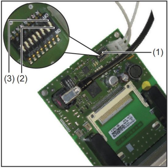
The dip-switch (1) on the robot interface RI FB Inside/i is used to configure
- the process data width
- the node address/IP address
At the factory all positions of the dip switch are set to OFF (3).
This corresponds to the binary value 0.
The position (2) corresponds to the binary value 1.
Configuration of the process data width
| Dip switch | Configuration | |||||||
| 8 | 7 | 6 | 5 | 4 | 3 | 2 | 1 | |
| OFF | OFF | – | – | – | – | – | – | Standard image 320 Bit |
| OFF | ON | – | – | – | – | – | – | Economy image 128 Bit |
| ON | OFF | – | – | – | – | – | – | Retro Fit Scope dependent on bus module |
| ON | ON | – | – | – | – | – | – | Not used |
The process data width defines the scope of the transferred data volume.
The kind of data volume that can be transferred depends on
- the robot controls
- the number of welding machines
- the type of welding machines
- “Intelligent Revolution”
- “Digital Revolution” (Retro Fit)
Set node address with dip switch (example)
| Dip switch | Node address | |||||||
| 8 | 7 | 6 | 5 | 4 | 3 | 2 | 1 | |
| – | – | OFF | OFF | OFF | OFF | OFF | ON | 1 |
| – | – | OFF | OFF | OFF | OFF | ON | OFF | 2 |
| – | – | OFF | OFF | OFF | OFF | ON | ON | 3 |
| – | – | ON | ON | ON | ON | ON | OFF | 62 |
| – | – | ON | ON | ON | ON | ON | ON | 63 |
The node address is set with positions 1 to 6 of the dip switch.
The configuration is carried out in binary format. This results in a configuration range of 1 to 63 in decimal format
NOTE!
After every change of the configurations of the dip switch settings, the inter- face needs to be restarted so that the changes will take effect.
(Restart = interrupting and restoring the power supply or executing the relevant function on the website of the power source)
Setting the IP Address
Upon delivery the node address is set to 0 using the dip switch.
This corresponds to the following IP settings:
- IP address: 0.0.0.0
- Subnet mask: 0.0.0.0
- Default gateway: 0.0.0.0
The IP address can be configured in two ways:
- Using the DIP switch within the range defined by 192.168.0.xx (xx = DIP switch setting = 1 to 63)
- If the dip switch is set to 0, using the following configuration tools:
- Using the website of the welding machine
NOTE!
If the IP address is again set to higher than 0 with the dip switch, the relevant IP address will be configured to the range of 1 to 63 after restarting the robot interface.
A node address previously configured by a configuration tool is overwritten.
NOTE!
If configurations have already been made, the network configurations can be restored to factory settings in two ways:
▶ set all dip switches back to 0
▶ with the button Restore factory settings on the website of the welding machine
The Website of the welding machine
The welding machine has its own website, the SmartManager.
As soon as the welding machine has been integrated into a network, the SmartManager can be opened via the IP address of the welding machine.
Depending on the system configuration and software upgrades, the SmartManager may contain the following entries:
- Overview
- Update
- Screenshot
- Save and restore
- Function packages
- Job data
- Overview of characteristics
- RI FB INSIDE/i
Call up the welding machine SmartManager and log in
- Presettings / System/Information ==> note down IP address of the welding machine
- Enter the IP address into the search field of the browser
- Enter username and password
Factory setting:
Username = admin
Password = admin - Confirm displayed message
The welding machine SmartManager is displayed.
Input and output signals
Data types
The following data types are used:
- UINT16 (Unsigned Integer)
Whole number in the range from 0 to 65535 - SINT16 (Signed Integer)
Whole number in the range from -32768 to 32767
Conversion examples:
- for a positive value (SINT16) e.g. desired wire speed x factor 12.3 m/min x 100 = 1230dec = 04CEhex
- for a negative value (SINT16) e.g. arc correction x factor -6.4 x 10 = -64dec = FFCOhex
Availability of Input Signals
The input signals listed below are available from firmware V4.1.x for all Inside/i systems.
Input signals (from robot to power source)
| Address | Signal | Activity / data type | Range | Factor | Process image | ||||
| Relative | Absolu- te | Standard | Economy | ||||||
| WORD | BYTE | BIT | BIT | ||||||
| 0 | 0 | 0 | 0 | Welding Start | Increa- sing | ||||
| 1 | 1 | Robot ready | High | ||||||
| 2 | 2 | Working mode Bit 0 | High | See table Value Range for Working Mode on page 44 | |||||
| 3 | 3 | Working mode Bit 1 | High | ||||||
| 4 | 4 | Working mode Bit 2 | High | ||||||
| 5 | 5 | Working mode Bit 3 | High | ||||||
| 6 | 6 | Working mode Bit 4 | High | ||||||
| 7 | 7 | — | |||||||
| 1 | 0 | 8 | Gas on | Increa- sing | |||||
| 1 | 9 | Wire forward | Increa- sing | ||||||
| 2 | 10 | Wire backward | Increa- sing | ||||||
| 3 | 11 | Error quit | Increa- sing | ||||||
| 4 | 12 | Touch sensing | High | ||||||
| 5 | 13 | Torch blow out | Increa- sing | ||||||
| 6 | 14 | Processline selection Bit 0 | High | See table Value range Process li- ne selection on page 45 | |||||
| 7 | 15 | Processline selection Bit 1 | High | ||||||
| Address | Signal | Activity / data type | Range | Factor | Process image | ||||
| Relative | Absolu- te | Standard | Economy | ||||||
| WORD | BYTE | BIT | BIT | ||||||
| 1 | 2 | 0 | 16 | Welding simulation | High | ||||
| 1 | 17 | Welding process MIG/MAG: 1) Synchro pulse on | High | ||||||
| Welding process WIG: 2) TAC on | High | ||||||||
| 2 | 18 | Welding process WIG: 2) Cap shaping | High | ||||||
| 3 | 19 | — | |||||||
| 4 | 20 | — | |||||||
| 5 | 21 | Booster manual | High | ||||||
| 6 | 22 | Wire brake on | High | ||||||
| 7 | 23 | Torchbody Xchange | High | ||||||
| 3 | 0 | 24 | — | ||||||
| 1 | 25 | Teach mode | High | ||||||
| 2 | 26 | — | |||||||
| 3 | 27 | — | |||||||
| 4 | 28 | — | |||||||
| 5 | 29 | Wire sense start | Increa- sing | ||||||
| 6 | 30 | Wire sense break | Increa- sing | ||||||
| 7 | 31 | — | |||||||
| Address | Signal | Activity / data type | Range | Factor | Process image | ||||
| Relative | Absolu- te | Standard | Economy | ||||||
| WORD | BYTE | BIT | BIT | ||||||
| 2 | 4 | 0 | 32 | TWIN mode Bit 0 | High | See table Value Range for TWIN Mode on page 45 | |||
| 1 | 33 | TWIN mode Bit 1 | High | ||||||
| 2 | 34 | — | |||||||
| 3 | 35 | — | |||||||
| 4 | 36 | — | |||||||
| 5 | 37 | Documentation mode | High | See table Value Range for Docu- mentation Mode on page 45 | |||||
| 6 | 38 | — | |||||||
| 7 | 39 | — | |||||||
| 5 | 0 | 40 | — | ||||||
| 1 | 41 | — | |||||||
| 2 | 42 | — | |||||||
| 3 | 43 | — | |||||||
| 4 | 44 | — | |||||||
| 5 | 45 | — | |||||||
| 6 | 46 | — | |||||||
| 7 | 47 | Disable process controlled correction | High | ||||||
| Address | Signal | Activity / data type | Range | Factor | Process image | ||||
| Relative | Absolu- te | Standard | Economy | ||||||
| WORD | BYTE | BIT | BIT | ||||||
| 3 | 6 | 0 | 48 | — | |||||
| 1 | 49 | — | |||||||
| 2 | 50 | — | |||||||
| 3 | 51 | — | |||||||
| 4 | 52 | — | |||||||
| 5 | 53 | — | |||||||
| 6 | 54 | — | |||||||
| 7 | 55 | — | |||||||
| 7 | 0 | 56 | ExtInput1 => OPT_Output 1 | High | |||||
| 1 | 57 | ExtInput2 => OPT_Output 2 | High | ||||||
| 2 | 58 | ExtInput3 => OPT_Output 3 | High | ||||||
| 3 | 59 | ExtInput4 => OPT_Output 4 | High | ||||||
| 4 | 60 | ExtInput5 => OPT_Output 5 | High | ||||||
| 5 | 61 | ExtInput6 => OPT_Output 6 | High | ||||||
| 6 | 62 | ExtInput7 => OPT_Output 7 | High | ||||||
| 7 | 63 | ExtInput8 => OPT_Output 8 | High | ||||||
| 4 | 8-9 | 0–7 | 64–79 | Welding characteristic- / Job number | UINT16 | 0 to 1000 | 1 | ||
| 5 | 10 – 11 | 0-7 | 80-95 | Welding process MIG/MAG: 1) Constant Wire: Wire feed speed command va- lue | SINT16 | -327,68 to 327,67 [m/min] | 100 | ||
| Welding process WIG: 2) Main- / Hotwire current com- mand value | UINT16 | 0 to 6553,5 [A] | 10 | ||||||
| For job-mode: Power correction | SINT16 | -20,00 to 20,00 [%] | 100 | ||||||
| Address | Signal | Activity / data type | Range | Factor | Process image | ||||
| Relative | Absolu- te | Standard | Economy | ||||||
| WORD | BYTE | BIT | BIT | ||||||
| 6 | 12 – 13 | 0-7 | 96-111 | Welding process MIG/MAG: 1) Arclength correction | SINT16 | -10,0 to 10,0 [Schritte] | 10 | ||
| Welding process MIG/MAG Standard-Manuel: Welding voltage | UINT16 | 0,0 to 6553,5 [V] | 10 | ||||||
| Welding process WIG: 2) Wire feed speed command va- lue | SINT16 | -327,68 to 327,67 [m/min] | 100 | ||||||
| For job-mode: Arclength correction | SINT16 | -10,0 to 10,0 [Schritte] | 10 | ||||||
| Welding process Constant Wire: Hotwire current | UINT16 | 0,0 to 6553,5 [A] | 10 | ||||||
| 7 | 14 – 15 | 0-7 | 112-127 | Welding process MIG/MAG: 1) Pulse-/dynamic correction | SINT16 | -10,0 to 10,0 [steps] | 10 | ||
| Welding process MIG/MAG Standard-Manuel: Dynamic | UINT16 | 0,0 to 10,0 [steps] | 10 | ||||||
| Welding process WIG: 2) Wire correction | SINT16 | -10,0 to 10,0 [steps] | 10 | ||||||
| 8 | 16 – 17 | 0-7 | 128-143 | Welding process MIG/MAG: 1) Wire retract correction | UINT16 | 0,0 to 10,0 [steps] | 10 | ||
| Welding process WIG: 2) Wire retract end | UINT16 | OFF, 1 to 50 [mm] | 1 | ||||||
| 9 | 18- 19 | 0-7 | 144-159 | Welding speed | UINT16 | 0,0 to 1000,0 [cm/min] | 10 | ||
| Address | Signal | Activity / data type | Range | Factor | Process image | ||||
| Relative | Absolu- te | Standard | Economy | ||||||
| WORD | BYTE | BIT | BIT | ||||||
| 10 | 20 – 21 | 0-7 | 160-175 | Process controlled correction | See table Value range for Pro- cess controlled correction on page 45 | ||||
| 11 | 22 – 23 | 0-7 | 176-191 | Welding process WIG: 2) Wire positioning start | |||||
| 12 | 24 – 25 | 0-7 | 192-207 | — | |||||
| 13 | 26 – 27 | 0-7 | 208-223 | — | |||||
| 14 | 28 – 29 | 0-7 | 224-239 | — | |||||
| 15 | 30 – 31 | 0-7 | 240-255 | Wire forward / backward length | UINT16 | OFF / 1 to 65535 [mm] | 1 | ||
| 16 | 32 – 33 | 0-7 | 256-271 | Wire sense edge detection | UINT16 | OFF / 0,5 to 20,0 [mm] | 10 | ||
| 17 | 34 – 35 | 0-7 | 272-287 | — | |||||
| 18 | 36 – 37 | 0-7 | 288-303 | — | |||||
| 19 | 38 – 39 | 0-7 | 304-319 | Seam number | UINT16 | 0 to 65535 | 1 | ||
- MIG/MAG Puls-Synergic, MIG/MAG Standard-Synergic, MIG/MAG Standard-Manuel, MIG/MAG PMC, MIG/MAG, LSC
- WIG coldwire, WIG hotwire
Value Range for Working Mode
| Bit 4 | Bit 3 | Bit 2 | Bit 1 | Bit 0 | Description |
| 0 | 0 | 0 | 0 | 0 | Internal parameter selection |
| 0 | 0 | 0 | 0 | 1 | Special 2-step mode characteristics |
| 0 | 0 | 0 | 1 | 0 | Job mode |
| 0 | 1 | 0 | 0 | 0 | 2-step mode characteristics |
| 0 | 1 | 0 | 0 | 1 | 2-step MIG/MAG standard manual |
| 1 | 0 | 0 | 0 | 0 | Idle Mode |
| 1 | 0 | 0 | 0 | 1 | Stop coolant pump |
| 1 | 1 | 0 | 0 | 1 | R/L-Measurement |
Value range for operating mode
Value range Process line selection
| Bit 1 | Bit 0 | Description |
| 0 | 0 | Process line 1 (default) |
| 0 | 1 | Process line 2 |
| 1 | 0 | Process line 3 |
| 1 | 1 | Reserved |
Value range for process line selection
Value Range for TWIN Mode
| Bit 1 | Bit 0 | Description |
| 0 | 0 | TWIN Single mode |
| 0 | 1 | TWIN Lead mode |
| 1 | 0 | TWIN Trail mode |
| 1 | 1 | Reserved |
Value range for TWIN mode
Value Range for Documentation Mode
| Bit 0 | Description |
| 0 | Seam number of welding machine (internal) |
| 1 | Seam number of robot (Word 19) |
Value range for documentation mode
Value range for Process controlled correction
| Process | Signal | Activity / data type | Value range configuration range | Unit | Factor |
| PMC | Arc length stabilizer | SINT16 | -327.8 to +327.7 0.0 to +5.0 | Volts | 10 |
Value range for process-dependent correction
Availability of Output Signals
The output signals listed below are available from firmware V4.1.x for all Inside/i systems.
Output Signals (from Power Source to Robot)
| Address | Signal | Activity / data type | Range | Factor | Process image | ||||
| relative | absolute | Standard | Economy | ||||||
| WORD | BYTE | BIT | BIT | ||||||
| 0 | 0 | 0 | 0 | Heartbeat Powersource | High/Low | 1 Hz | |||
| 1 | 1 | Power source ready | High | ||||||
| 2 | 2 | Warning | High | ||||||
| 3 | 3 | Process active | High | ||||||
| 4 | 4 | Current flow | High | ||||||
| 5 | 5 | Arc stable- / touch signal | High | ||||||
| 6 | 6 | Main current signal | High | ||||||
| 7 | 7 | Touch signal | High | ||||||
| 1 | 0 | 8 | Collisionbox active | High | 0 = collisi- on or ca- ble break | ||||
| 1 | 9 | Robot Motion Release | High | ||||||
| 2 | 10 | Wire stick workpiece | High | ||||||
| 3 | 11 | — | |||||||
| 4 | 12 | Short circuit contact tip | High | ||||||
| 5 | 13 | Parameter selection in- ternally | High | ||||||
| 6 | 14 | Characteristic number valid | High | ||||||
| 7 | 15 | Torch body gripped | High | ||||||
| Address | Signal | Activity / data type | Range | Factor | Process image | ||||
| relative | absolute | Standard | Economy | ||||||
| WORD | BYTE | BIT | BIT | ||||||
| 1 | 2 | 0 | 16 | Command value out of range | High | ||||
| 1 | 17 | Correction out of range | High | ||||||
| 2 | 18 | — | |||||||
| 3 | 19 | Limitsignal | High | ||||||
| 4 | 20 | — | |||||||
| 5 | 21 | — | |||||||
| 6 | 22 | Main supply status | Low | ||||||
| 7 | 23 | — | |||||||
| 3 | 0 | 24 | Sensor status 1 | High | See table Assign- ment of Sensor Sta- tuses 1–4 on page 49 | ||||
| 1 | 25 | Sensor status 2 | High | ||||||
| 2 | 26 | Sensor status 3 | High | ||||||
| 3 | 27 | Sensor status 4 | High | ||||||
| 4 | 28 | — | |||||||
| 5 | 29 | — | |||||||
| 6 | 30 | — | |||||||
| 7 | 31 | — | |||||||
| 2 | 4 | 0 | 32 | — | |||||
| 1 | 33 | — | |||||||
| 2 | 34 | — | |||||||
| 3 | 35 | Safety status Bit 0 | High | See table Value ran- ge Safety status on page 50 | |||||
| 4 | 36 | Safety status Bit 1 | High | ||||||
| 5 | 37 | — | |||||||
| 6 | 38 | Notification | High | ||||||
| 7 | 39 | System not ready | High | ||||||
| 5 | 0 | 40 | — | ||||||
| 1 | 41 | — | |||||||
| 2 | 42 | — | |||||||
| 3 | 43 | — | |||||||
| 4 | 44 | — | |||||||
| 5 | 45 | — | |||||||
| 6 | 46 | — | |||||||
| 7 | 47 | — | |||||||
| Address | Signal | Activity / data type | Range | Factor | Process image | ||||
| relative | absolute | Standard | Economy | ||||||
| WORD | BYTE | BIT | BIT | ||||||
| 3 | 6 | 0 | 48 | Process Bit 0 | High | See table Value Range for Process Bit on page 50 | |||
| 1 | 49 | Process Bit 1 | High | ||||||
| 2 | 50 | Process Bit 2 | High | ||||||
| 3 | 51 | Process Bit 3 | High | ||||||
| 4 | 52 | Process Bit 4 | High | ||||||
| 5 | 53 | — | |||||||
| 6 | 54 | Touch signal gas nozzle | High | ||||||
| 7 | 55 | TWIN synchronization active | High | ||||||
| 7 | 0 | 56 | ExtOutput1 <= OPT_In- put1 | High | |||||
| 1 | 57 | ExtOutput2 <= OPT_In- put2 | High | ||||||
| 2 | 58 | ExtOutput3 <= OPT_In- put3 | High | ||||||
| 3 | 59 | ExtOutput4 <= OPT_In- put4 | High | ||||||
| 4 | 60 | ExtOutput5 <= OPT_In- put5 | High | ||||||
| 5 | 61 | ExtOutput6 <= OPT_In- put6 | High | ||||||
| 6 | 62 | ExtOutput7 <= OPT_In- put7 | High | ||||||
| 7 | 63 | ExtOutput8 <= OPT_In- put8 | High | ||||||
| 4 | 8- 9 | 0-7 | 64-79 | Welding voltage | UINT16 | 0.0 to 655.35 [V] | 100 | ||
| 5 | 10 – 11 | 0-7 | 80-95 | Welding current | UINT16 | 0.0 to 6553.5 [A] | 10 | ||
| 6 | 12 – 13 | 0-7 | 96-111 | Wire feed speed | SINT16 | -327.68 to 327.67 [m/ min] | 100 | ||
| 7 | 14 – 15 | 0-7 | 112-127 | Actual real value for seam tracking | UINT16 | 0 to 6.5535 | 10000 | ||
| 8 | 16 – 17 | 0-7 | 128-143 | Error number | UINT16 | 0 to 65535 | 1 | ||
| 9 | 18 – 19 | 0-7 | 144-159 | Warning number | UINT16 | 0 to 65535 | 1 | ||
| Address | Signal | Activity / data type | Range | Factor | Process image | ||||
| relative | absolute | Standard | Economy | ||||||
| WORD | BYTE | BIT | BIT | ||||||
| 10 | 20 – 21 | 0-7 | 160-175 | Motor current M1 | SINT16 | -327.68 to 327.67 [A] | 100 | ||
| 11 | 22 – 23 | 0-7 | 176-191 | Motor current M2 | SINT16 | -327.68 to 327.67 [A] | 100 | ||
| 12 | 24 – 25 | 0-7 | 192-207 | Motor current M3 | SINT16 | -327.68 to 327.67 [A] | 100 | ||
| 13 | 26 – 27 | 0-7 | 208-223 | — | |||||
| 14 | 28 – 29 | 0-7 | 224-239 | — | |||||
| 15 | 30 – 31 | 0-7 | 240-255 | — | |||||
| 16 | 32 – 33 | 0-7 | 256-271 | Wire position | SINT16 | -327.68 to 327.67 [mm] | 100 | ||
| 17 | 34 – 35 | 0-7 | 272-287 | — | |||||
| 18 | 36 – 37 | 0-7 | 288-303 | — | |||||
| 19 | 38 – 39 | 0-7 | 304-319 | — | |||||
Assignment of Sensor Statuses 1–4
| Signal | Description |
| Sensor status 1 | OPT/i WF R wire end (4,100,869) |
| Sensor status 2 | OPT/i WF R wire drum (4,100,879) |
| Sensor status 3 | OPT/i WF R ring sensor (4,100,878) |
| Sensor status 4 | Wire buffer set CMT TPS/i (4,001,763) |
Assignment of sensor statuses
Value range Safety status
| Bit 1 | Bit 0 | Description |
| 0 | 0 | Reserve |
| 0 | 1 | Hold |
| 1 | 0 | Stop |
| 1 | 1 | Not installed / active |
Value range Safety status
Value Range for Process Bit
| Bit 4 | Bit 3 | Bit 2 | Bit 1 | Bit 0 | Description |
| 0 | 0 | 0 | 0 | 0 | No internal parameter selection or process |
| 0 | 0 | 0 | 0 | 1 | MIG/MAG pulse synergic |
| 0 | 0 | 0 | 1 | 0 | MIG/MAG standard synergic |
| 0 | 0 | 0 | 1 | 1 | MIG/MAG PMC |
| 0 | 0 | 1 | 0 | 0 | MIG/MAG LSC |
| 0 | 0 | 1 | 0 | 1 | MIG/MAG standard manual |
| 0 | 0 | 1 | 1 | 0 | Electrode |
| 0 | 0 | 1 | 1 | 1 | TIG |
| 0 | 1 | 0 | 0 | 0 | CMT |
| 0 | 1 | 0 | 0 | 1 | ConstantWire |
| 0 | 1 | 0 | 1 | 0 | ColdWire |
| 0 | 1 | 0 | 1 | 1 | DynamicWire |
Value Range for Process Bit
Value Range for Function status
| Bit 1 | Bit 0 | Description |
| 0 | 0 | Inactive |
| 0 | 1 | Idle |
| 1 | 0 | Finished |
| 1 | 1 | Error |
Value range for function status
Retrofit Image Input and Output Signals
Input Signals
The signals listed below are available from firmware V1.6.0 for all Inside/i systems.
| Serial no. | Signal designation | Range | Action |
| E01 | Welding on | High | |
| E02 | Robot ready | High | |
| E03 | Operating mode bit 0 | See table Value range for opera- ting modes on page 52 | High |
| E04 | Operating mode bit 1 | High | |
| E05 | Operating mode bit 2 | High | |
| E06 | — | ||
| E07 | — | ||
| E08 | — | ||
| E09 | Gas test | High | |
| E10 | Wire forward | High | |
| E11 | Wire backward | High | |
| E12 | Error quit | High | |
| E13 | Position search | High | |
| E14 | Purge welding torch | High | |
| E15 | — | ||
| E16 | — | ||
| E17 – E24 | Job number | 0 to 99 | |
| E25 – E31 | Program number | 1 to 127 | |
| E32 | Welding simulation | High | |
| Only in Job mode (E17 – E32): | |||
| E17 – E31 | Job number | 0 to 999 | |
| E32 | Welding simulation | High | |
| E33 – E40 | Output set value – Low byte | 0 to 65535 (0 to 100%) | |
| E41 – E48 | Output set value – High byte | ||
| E49 – E56 | Arc length correction, set value Low byte | 0 to 65535 (-30 to +30%) | |
| E57–E64 | Arc length correction, set value High byte | ||
| E65 – E72 | Pulse or dynamic correction | 0 to 255 (-5 to +5%) | |
| E73–E80 | — | ||
| E81 – E88 | — | ||
| E89 – E96 | — | ||
| Serial no. | Signal designation | Range | Action |
| E97 – E104 | Welding speed – Low byte | 0 to 65535 (0 to 6553.5 cm/ min) | |
| E105 – E112 | Welding speed – High byte | ||
| E113 | SynchroPulse on | High | |
| E114 | — | ||
| E115 | — | ||
| E116 | — | ||
| E117 | Output full range (0 to 30 m) | High | |
| E118 | — | ||
| E119 | — | ||
| E120 | — | ||
| E121 – E128 | — | ||
| E129 – E296 | — |
Value range for operating modes
| Bit 2 | Bit 1 | Bit 0 | Description |
| 0 | 0 | 0 | MIG/MAG Synergic welding |
| 0 | 0 | 1 | MIG/MAG Synergic welding |
| 0 | 1 | 0 | Job mode |
| 0 | 1 | 1 | Internal parameter selection |
Output Signals
The signals listed below are available from firmware V1.6.0 for all Inside/i systems.
| Seq. no | Signal designation | Range | Action |
| A01 | Arc stable | High | |
| A02 | Limit signal | High | |
| A03 | Process active | High | |
| A04 | Main current signal | High | |
| A05 | Welding torch collision protection | High | |
| A06 | Power source ready | High | |
| A07 | Communication ready | High | |
| A08 | Life Cycle Toggle Bit (250ms) | High | |
| A09 – A16 | — | ||
| A17 – A24 | — | ||
| A25 | — |
| Seq. no | Signal designation | Range | Action |
| A26 | — | ||
| A27 | — | ||
| A28 | Wire present | ||
| A29 | Short circuit time exceeded | High | |
| A30 | — | ||
| A31 | — | ||
| A32 | Power out of range | High | |
| A33 – A40 | Welding voltage actual value – Low byte | 0 to 65535 (0 to 100 V) | |
| A41 – A48 | Welding voltage actual value – High byte | ||
| A49 – A56 | Welding current actual value – Low byte | 0 to 65535 (0 to 1000 A) | |
| A57 – A64 | Welding current actual value – High byte | ||
| A65 – A72 | Motor current | 0 to 255 (0 to 5 A) | |
| A73 – A80 | — | ||
| A81 – A88 | — | ||
| A89 – A96 | — | ||
| A97 – A104 | Wire speed – Low byte | 0 to vDmax | |
| A105 – A112 | Wire speed – High byte | ||
| A113 – A120 | — | ||
| A121 – A128 | — | ||
| A129 – A296 | — |
![]()
 42,0410,1916
037-17072024 spareparts.fronius.com
![]() SPARE PARTS ONLINE
SPARE PARTS ONLINE
Fronius International GmbH
Froniusstrafve 1
4643 Pettenbach Austria
contact@fronius.com
www.fronius.com
At www.fronius.com/contact you will find the contact details
of all Fronius subsidiaries and Sales & Service Partners.
Documents / Resources
 | Fronius RI FB Inside Bus Module [pdf] Instruction Manual 42, 0410, 1916, RI FB Inside Bus Module, RI FB Inside, Bus Module, Module |