![]() Front View Millimeter Wave Radar
Front View Millimeter Wave Radar
FVR30 Product Specification
No:RPS-003
Version:V2.4
Released date:
2023-8-2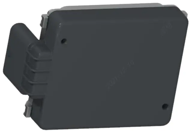 V2.4
V2.4
Revised Record
| Version | Revised date | Author | Revised contents |
| V1.0 | 2021.1.21 | Lv Wei | Created the first version. |
| V1.1 | 2021.1.21 | Lin Xiaomeng | Updated the communication voltage range. Updated normal current and power consumption. Updated the Pin9 definition. |
| V1.2 | 2021.1.22 | Lin Xiaomeng | Updated the maximum current and power consumption. |
| V1.3 | 2021.7.28 | Gao Shimeng | Updated documentation based on the latest hardware information. |
| V1.4 | 2021.7.28 | Gao Shimeng | Updated radar dimension and mass information. |
| V1.5 | 2021.11.18 | Gao Shimeng | Updated product image. |
| V1.6 | 2021.12.10 | Gao Shimeng | Updated the product mechanic configuration. |
| V1.7 | 2021.12.29 | Li Mei | Updated the figure of exploded view. |
| V1.8 | 2022.01.05 | Li Mei | Updated radar characteristic table. |
| V1.9 | 2022.04.14 | Li Mei | Updated the FOV diagram. |
| V2.0 | 2022.09.15 | Li Mei | Updated the structural dimension drawing. |
| V2.1 | 2022.10.9 | Li Mei | Updated the angular resolution. |
| V2.2 | 2023.1.4 | Li Mei | Updated FOV diagram and radar characteristic table. |
| V2.3 | 2023.8.1 | Li Haojun Jin Yitong | Updated English Version. |
| V2.4 | 2023.8.2 | Jin Yitong | Updated some English translations. |
Overview
FVR30 is a front view millimeter wave radar product developed by Freetech based on the latest generation of RF chip solutions, which adopts a radar specific high-performance MMIC+MCU hardware architecture with three transmitting and four receiving antennas. The sensing performance is benchmarked to the international first-line radar products. The radar has two CAN channels, and supports HS-CAN or CAN-FD communication. The series radars are suitable for Level1-Level4 autonomous driving scenarios and meet the ASIL-B functional safety level.
This document is FVR30 millimeter wave radar product specification, which mainly describes the product structure, technical indicators and functions that can be realized.
Hardware
Mechanical principle
The FVR30 radar product is designed with single board PCB, which is highly integrated with the RF antenna and signal processing circuit. The FVR30 radar is composed of a housing, heatsink, PCBA, shielding, radome, etc., as shown in the figure below. The radome and the housing are connected by laser welding technology, forming a sealed space to protect the electronic device inside, and also provides a terminal interface connector to the vehicle.
| Numbe | Name |
| 1 | ST3*12 Self-tapping screws |
| 2 | Radome |
| 3 | Waterproof breathable membrane |
| 4 | Shielding |
| 5 | ST3*6 Self-tapping screw |
| 6 | PCBA |
| 7 | Heat-conducting glue |
| 8 | Glue |
| 9 | Heatsink |
| 10 | Label |
The basic mechanic configuration of radar is as follows:

2.2 Circuit design
The FVR30 radar uses TI’s high-performance millimeter wave radar processor AM2732 (DSP) and an AWR2243 (MMIC) with three transmitting channels and four receiving channels. It has SPT hardware acceleration units and a 6-bit phase shifter. The hardware block diagram is shown in the following figure.

Dimension and mass
FVR30 radar basic dimensions are: 100 x 70 x 20 mm. Mass is about 160g. Specific dimension is shown as the figure below (in mm).

Interface
FVR30 radar uses 7-pin interface, and the pin positions are shown as the figure below:
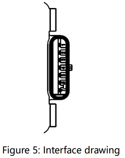
Detailed radar connector pin definitions are as below:
| Number | Definition | Description of functions |
| 1 | GND | GND |
| 2 | CAN(FD)1-H | Vehicle CAN High |
| 3 | CAN(FD)1-L | Vehicle CAN Low |
| 4 | KL15 Wakeup | KL15Wakeup |
| 5 | CAN(FD)2-H | Private CAN High |
| 6 | CAN(FD)2-L | Private CAN Low |
| 7 | NA | NA |
Table 1: Pin defination
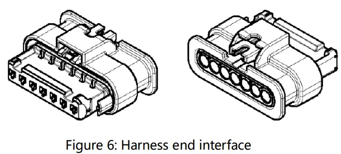
Harness-End interface: Type: Sumitomo – 61897895
Working state
5.1 Power consumption
Current and power consumption at a supply voltage of 12V are stated in Table 2:
| Sleep mode | Normal operation | Peak power | |
| Current | <100 uA | 410 mA (typically) | 620 mA |
| Power | – | 4.5 W (typically) | <7 W |
5.2 Voltage supply operation modes
For the 12V variant of the sensor, the behavior for different supply voltage conditions are given in Table 3:
| Voltage | Communication state | Hardware monitor | Over-voltage protection |
| <6V | Unable to communicate | Unable to monitor | Inactive |
| 6V~9V | LowVoltage | LowVoltage (storing of fault “undervoltage”) | Inactive |
| 9V~16V | Normal | Normal | Inactive |
| 16V~18V | HighVoltage | HighVoltage (storing of fault “overvoltage”) | Inactive |
| >18V | Unable to communicate | Unable to communicate | Active |
Table3: Voltage supply operation modes
5.3 Wake-up modes
Either a CAN wake-up or hardwire wake-up (KL15) can be used for FVR30 sensor.
5.4 Environment parameters
FVR30 radar related environment parameters are as below:
- Storage temperature: -40℃ ~ 105℃
- Operating temperature: -40℃ ~ 85℃
- Function limited operating temperature: 85℃ ~ 95℃
5.5 Calibration method
FVR30 radar supports static calibration, dynamic calibration and self-calibration of azimuth installation angle.
- Static calibration is carried out by special calibration equipment when the vehicle is off the assembly line.
- Dynamic calibration is generally used after the vehicle is off the line, or 4S after-sales maintenance, through a specific calibration road, after driving some distance, automatically complete the calculation of the calibration angle.
- Self-calibration is that the vehicle automatically identifies the external environment during normal driving, and automatically self-calibrates when the calibration conditions are met.
5.6 Installation Instruction
FVR30 radar is fixed to the body by a mounting bracket, as shown in the figure below:

The safe distance of the radar mount from the radar edge is 5mm.
A “second surface” (usually the car logo, bumper, and specially designed radar radome) needs to exist between the radar sensor and the exterior of the car to avoid the sensor from stone impact and ultraviolet radiation. The radar cannot be left open without a second surface.
The position and orientation of the radar relative to the second surface cannot usually be specified in detail, but can be evaluated separately depending on the application. The optimal system performance of the second surface depends on the following factors:
- Thickness
- Material
- Form
- Distance
- Uniformity
- Degree of inclination and curvature
- Paint
The customer needs to provide enough second surface samples. For cases where the second surface is a bumper, the customer needs to provide various bumper configurations, covered with different paints and varnishes. Experience shows that white and silver paints have high amount of metal particles and therefore have a greater impact on radar signals. Snow on the second surface causes degradation of the quality of the radar signals. In order to reduce accumulated snow, the second surface cannot be designed with horizontal gaps and grooves.
Perception performance
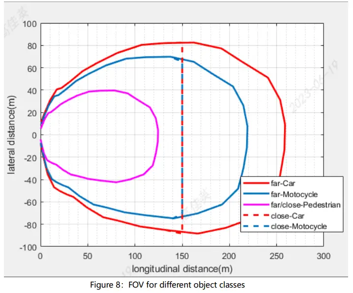
FVR30 radar can detect object with RCS (radar cross-section) between – 10~+ 40dBsm.
The FOV (field of view) diagram is as follows:
Radar detection characteristic design targets are depicted in Table 4:
| Characteristic Product | FVR30 Test value (field test) | |
| Range | Range (m) | 0.25-260 (@0°car) 125 (@0°pedestrian) |
| Accuracy (m) | 0.17/0.24 | |
| Resolution (m) | 0.3/0.6 | |
| Velocity | Range (m/s) | -110…+55 |
| Accuracy (m/s) | 0.07 | |
| Resolution (m/s) | 0.15 | |
| Azimuth angle | Range C) | -60…60 |
| Accuracy (°) | 0.2 | |
| Resolution (°) | 4. | |
| Elevation angle | Range C) | -10…+10 |
| Accuracy C) | <1 (0.45°) | |
| Resolution C) | NA | |
| Operating frequency | Frequency(GHz) | 76-77 |
Table 4: Radar characteristic design targets
Radar application function
The FVR30 radar can support the output of radar perception signal, as well as the output of the original point trace signal and the target signal after cluster tracking. These perception signals can be sent to cameras or domain controllers to implement relevant intelligent driving functions.
Caution notice of certification
Please take attention that changes or modification not expressly approved by the party responsible for compliance could void the user’s authority to operate the equipment.
This device complies with Part 15 of the FCC Rules. Operation is subject to the following two conditions: (1) This device may not cause harmful interference, and (2) This device must accept any interference received, including interference that may cause undesired operation. This equipment complies with FCC radiation exposure limits set forth for an uncontrolled environment. This equipment should be installed and operated with minimum distance 20cm between the radiator & your body.
Freetech Intelligent Systems Co., Ltd.
Documents / Resources
 | freetech NoRPS-003 Front View Millimeter Wave Radar [pdf] User Manual NoRPS-003 Front View Millimeter Wave Radar, NoRPS-003, Front View Millimeter Wave Radar, Millimeter Wave Radar, Wave Radar |


