1. Introduction
The FNIRSI DST-210 is a compact and versatile 3-in-1 handheld device designed for electronic testing and measurement. It integrates the functions of a digital oscilloscope, a true RMS multimeter, and a signal generator into a single portable unit. This manual provides detailed instructions to help you effectively use and maintain your device.
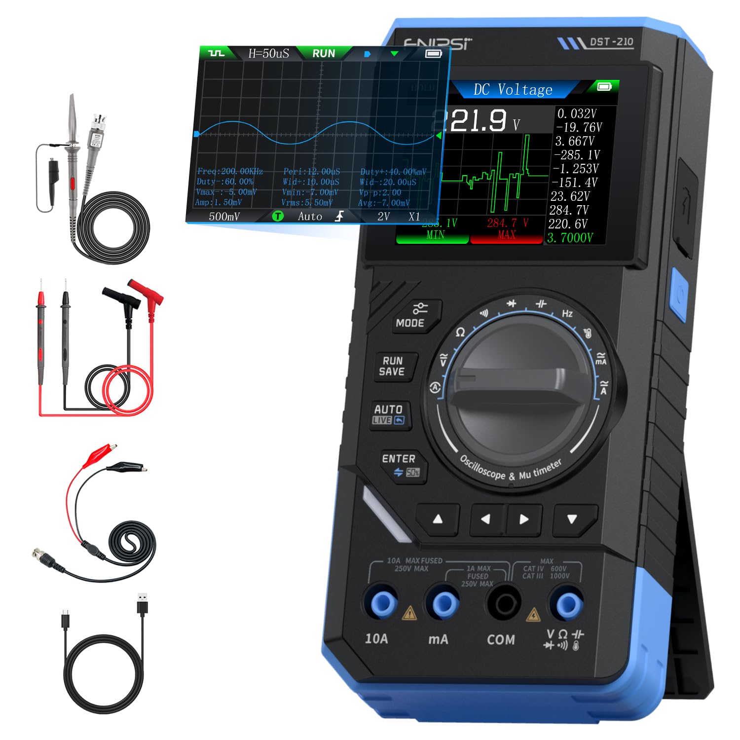
Figure 1: FNIRSI DST-210 3-in-1 Handheld Device
2. Produit terminéview
2.1 Principales caractéristiques
- Fonctionnalité 3 en 1 : Combines a digital oscilloscope, a true RMS multimeter, and a signal generator.
- Afficher: 2.8-inch TFT color LCD for clear data visualization.
- Oscilloscope: 10MHz analog bandwidth, 48MSa/s real-time sampling rate, supports Auto/Normal/Single trigger modes, waveform image saving and display.
- Multimètre: 19999-count true RMS measurement for DC/AC voltage, DC/AC current, resistance, capacitance, frequency, temperature, diode, and continuity. Features data hold, record mode with graphical display, and LIVE function for voltagdétection de présence.
- Générateur de signaux : Outputs 13 types of waveforms (Sine, Square, Sawtooth, Half-wave, Full-wave, Step, Reverse Step, Index Up/Down, DC, Multi-audio, Sink Pulse, Lorentz Wave) with adjustable frequency (0-50KHz), ampamplitude (0.1-3.0V) et rapport cyclique (0-100%).
- Portabilité: Compact design with an integrated stand, powered by a 3000mAh rechargeable lithium battery providing up to 10 hours of continuous use. Type-C charging supported.
2.2 Contenu du paquet
Vérifiez que tous les éléments sont présents dans le colis :
- FNIRSI DST-210 Main Unit
- P6100 Haut Voltage Sonde
- Cordons de test (rouge et noir)
- Pinces crocodiles
- Câble de charge de type C
- Instruction Manual (PDF version available online)
- Boîte d'emballage

Figure 2 : Accessoires inclus
3. Installation
3.1 Chargement de l'appareil
Before initial use, fully charge the DST-210. Connect the provided Type-C charging cable to the device's Type-C port and a compatible USB power adapter (5V/1A). The battery indicator on the display will show charging status.
3.2 Connexion des sondes
For accurate measurements, ensure probes are correctly connected:
- Multimeter Measurements: Insert the red test lead into the VΩHzmA or 10A jack (depending on the measurement) and the black test lead into the COM jack.
- Oscilloscope Measurements: Connectez le haut volume P6100tage probe to the oscilloscope input jack. Ensure the probe's attenuation setting (e.g., X1 or X10) matches the device's setting for accurate readings.
- Sortie du générateur de signaux : Connect the output cable to the signal generator output port.

Figure 3: Input Jacks and Controls
4. Mode d'emploi
4.1 Mise sous/hors tension
Press and hold the power button (located on the side) to turn the device on or off.
4.2 Sélection du mode
Rotate the central knob to switch between Multimeter, Oscilloscope, and Signal Generator modes. Within each mode, further sub-functions can be selected using the knob or dedicated buttons.

Figure 4: Using the Oscilloscope Function
4.3 Fonctionnement du multimètre
In Multimeter mode, the device offers various measurement functions:
- Voltage/Current (DC/AC): Select the appropriate DC V, AC V, DC A, or AC A setting. Connect test leads to the circuit. The device supports a record mode that displays measurement trends graphically, and can store up to 10 sets of data.
- Résistance (Ω) : Select the resistance function. Connect test leads across the component.
- Capacité (F): Select the capacitance function. Connect test leads across the capacitor.
- Fréquence (Hz) : Select the frequency function. Connect test leads to the signal source.
- Test de diodes : Select the diode function. Connect test leads across the diode to check its forward voltage goutte.
- Test de continuité : Select the continuity function. Connect test leads across a conductor; a beep indicates continuity.
- Température: Use a K-type thermocouple (not included) connected to the appropriate jacks for temperature measurement.
- LIVE Function: For single-probe voltagdétection de présence.

Figure 5: Multimeter Measurement Examples
4.4 Fonctionnement de l'oscilloscope
In Oscilloscope mode, the device displays waveforms:
- Affichage de la forme d'onde : Connect the oscilloscope probe to the circuit. The device automatically adjusts settings for stable waveform display.
- Modes de déclenchement : Select between Auto, Normal, and Single trigger modes to capture different types of signals.
- Enregistrement de la forme d'onde : Press the 'RUN/SAVE' button to save the current waveform image. Saved images can be reviewédité et exporté.

Figure 6: Oscilloscope Waveform Display
4.5 Fonctionnement du générateur de signaux
In Signal Generator mode, the device outputs various waveforms:
- Sélection de la forme d'onde : Choose from 13 different waveform types using the menu options.
- Ajustement des paramètres : Adjust the frequency (0-50KHz), amplitude (0.1-3.0V), and duty cycle (0-100%) as required for your application.

Figure 7: Signal Generator Waveform Selection
4.6 PC Connection and Data Export
The DST-210 can connect to a PC via its Type-C USB port for data management and firmware updates.
- Waveform Screenshots: Long-press the 'RUN/SAVE' button to save waveform screenshots.
- Exportation de données : Connect the device to a computer to view, save, and export recorded waveform images and data.
- Mises à jour du micrologiciel : Consultez régulièrement le site officiel du FNIRSI. website for firmware updates to ensure optimal performance and access to new features. Follow the instructions provided with the firmware update package.

Figure 8: PC Connection for Data Management
5. Entretien
- Nettoyage: Utilisez un chiffon doux et sec pour nettoyer l'appareil. N'utilisez pas de nettoyants abrasifs ni de solvants.
- Stockage: Conservez l'appareil dans un endroit frais et sec, à l'abri de la lumière directe du soleil et des températures extrêmes.
- Entretien de la batterie: Pour prolonger la durée de vie de la batterie, évitez de la décharger complètement trop souvent. Chargez l'appareil régulièrement, même en cas de non-utilisation prolongée.
- Entretien de la sonde : Inspect test leads and probes for damage before each use. Replace any damaged accessories immediately.
6. Dépannage
| Problème | Cause possible | Solution |
|---|---|---|
| L'appareil ne s'allume pas. | Batterie faible ou bouton d'alimentation défectueux. | Charge the device fully. If the issue persists, contact support. |
| Unstable or inaccurate readings in Multimeter mode. | Poor probe connection, incorrect mode selection, or external interference. | Ensure probes are securely connected. Verify the correct measurement mode is selected. Minimize external electrical interference. |
| Oscilloscope waveform is not stable. | Incorrect trigger settings or probe attenuation. | Adjust trigger level and mode. Ensure probe attenuation (X1/X10) matches the device setting. |
| Le signal de sortie du générateur est incorrect. | Incorrect waveform type, frequency, ampparamètres de litude ou de cycle de service. | Verify all signal generator parameters are set as desired. |
| Impossible de se connecter à l'ordinateur ou d'exporter des données. | Faulty USB cable, incorrect PC driver, or software issue. | Try a different Type-C cable. Ensure necessary drivers are installed on your PC. Refer to the official webSite de téléchargement de logiciels et de pilotes. |
7. Spécifications
7.1 Paramètres de l'oscilloscope
| Catégorie | Spécification |
|---|---|
| S en temps réelampTaux de ling | 48 MSa / s |
| Bande passante analogique | 10 MHz |
| Impédance d'entrée | 1 MΩ |
| Méthode de couplage | CA/CC |
| Volume de mesuretaget gamme | 1:1 Probe: ±80Vpp (±40V), 10:1 Probe: ±800Vpp (±400V) |
| Sensibilité verticale | 10mV/div ~ 10V/div (at X1) |
| Décalage vertical | Adjustable (with indicator) |
| Plage de base de temps horizontale | 50 ns ~ 20 s |
| Mode de déclenchement | Auto, Normal, Simple |
| Déclencheur de bord | Bord ascendant/de chute |
| Niveau de declenchement | Adjustable (with indicator) |
| Gel de la forme d'onde | Supported (HOLD function) |
| Mesure automatique | Max, Min, Average, RMS, Peak-to-Peak, Frequency, Duty Cycle, etc. |
7.2 Paramètres du multimètre
| Fonction de mesure | Gamme | Précision |
|---|---|---|
| Vol CCtage | 1.9999V/19.999V/199.99V/1000V | ±(0.5%+3) |
| Vol ACtage | 1.9999V/19.999V/199.99V/750V | ±(1.0%+3) |
| Courant continu | 19.999 mA/199.99 mA/1.9999A/9.999A | ±(1.2%+3) |
| Courant alternatif | 19.999 mA/199.99 mA/1.9999A/9.999A | ±(1.5%+3) |
| Résistance | 19.999MΩ/199.99kΩ/19.999kΩ | ±(2.0%+5) |
| Capacitance | 999.9uF/99.99uF/9.999uF/999.9nF/99.99nF, 9.999mF/99.99mF | ±(2.0%+5) |
| Fréquence | 9.999MHz/999.9kHz/99.99kHz/9.999kHz/999.9Hz/99.99Hz | ±(0.1%+2) |
| Température | [-55~1300°C] / [-67~2372°F] | ±(2.5%+5) |
| Diode/Continuité | Soutenu | N / A |
| Fonction LIVE | Soutenu | N / A |
7.3 Paramètres du générateur de signaux
| Catégorie | Spécification |
|---|---|
| Formes d'onde de sortie | 13 types |
| Fréquence de la forme d'onde | 0 ~ 50KHz |
| Cycle de service | 0 ~ 100% (adjustable) |
| Forme d'onde Amplatitude | 0.1 ~ 3.0 V |
7.4 Spécifications générales
| Catégorie | Spécification |
|---|---|
| Modèle de produit | DST-210 |
| Afficher | Écran couleur TFT de 2.8 pouce |
| Rétroéclairage | Luminosité réglable |
| Alimentation électrique | Type-C (5V/1A) |
| Batterie | 3000mAh |
| Prise en charge linguistique | chinois, anglais |
| Taille du produit | Environ 177.43 mm x 87 mm x 35 mm |
| Poids du produit | Environ 300 g |
8. Garantie et assistance
For any questions, issues, or support needs regarding your FNIRSI DST-210, please contact us through the following methods:
- Message Amazon : If you purchased the product on Amazon, you can contact us via the Amazon messaging system. Go to your 'Order History', select the relevant order, and click 'Problem with order' or 'Contact Seller'.
- Assistance par e-mail : You can also reach our after-sales service center directly via email at support@fnirsi.com. Please include your order number and a detailed description of your issue for faster assistance.
When attaching large photos or videos, email support is recommended due to potential attachment size limits on Amazon's messaging system.
Video 1: Demonstration of FNIRSI DST-210's Multimeter, Oscilloscope, and Signal Generator Functions.