1. Produit terminéview
The GOWENIC A780+ is an ATX desktop motherboard designed to support LGA940 and 938 pin processors, including AMD AM2, AM2+, AM3, and FX series CPUs. It features dual-channel DDR3 memory support, allowing for a maximum capacity of 32GB, and includes a PCIE 16X Gen 3.0 graphics card slot for enhanced visual performance.
This motherboard is constructed with a rugged PCB material and an all-solid state panel, ensuring durability and a long lifespan. Its multi-phase power supply delivers stable and accurate power distribution, optimizing CPU performance. Advanced thermal solutions are integrated for efficient heat dissipation, contributing to system stability and longevity.
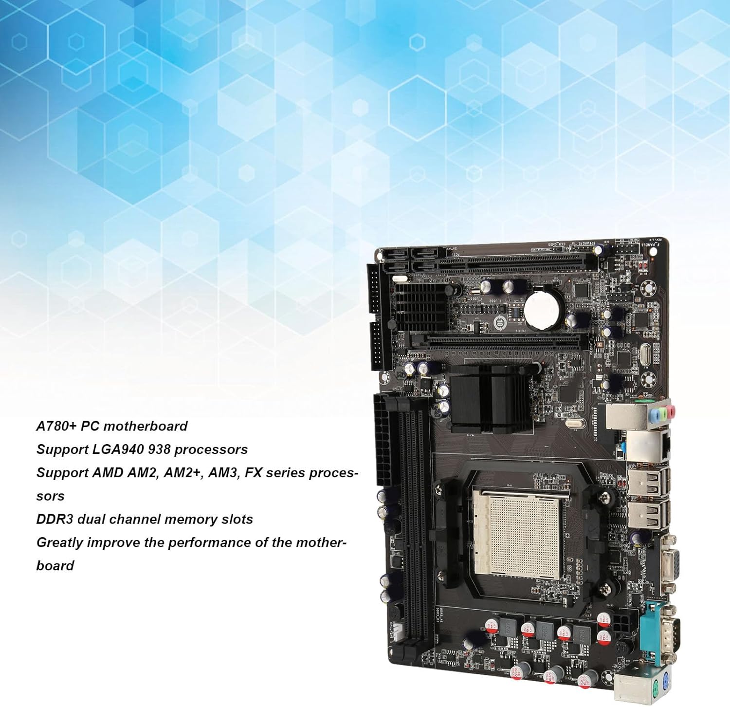
Figure 1 : Généralités view of the GOWENIC A780+ PC Motherboard.
2. Contenu du colis
Veuillez vérifier que tous les articles énumérés ci-dessous sont inclus dans votre colis. Si un article est manquant ou endommagé, veuillez contacter votre revendeur.
- 1 x GOWENIC A780+ Desktop Motherboard
- 1 x déflecteur d'E/S
- 1 x câble de données SATA

Figure 2: Motherboard with I/O baffle and SATA cable.
3. Disposition et composants de la carte mère
Familiarize yourself with the various components and connectors on the A780+ motherboard before installation.

Figure 3: Detailed layout of the A780+ motherboard with key component labels.
- 4 PIN CPU Power Supply: Connects to the CPU power cable from the power supply unit.
- PS/2 Mouse Button Interface: For connecting legacy PS/2 mice.
- Port COM: Port de communication série.
- VGA: Video Graphics Array output port.
- USB2.0*4: Four USB 2.0 ports for peripheral connections.
- 100 Megabit Network Card: Port Ethernet pour la connectivité réseau.
- Interface audio: Audio input/output jacks.
- USB2.0 Front Interface: Header for front panel USB 2.0 ports.
- Front Sound Interface: Header for front panel audio jacks.
- Interface du panneau avant : Header for power button, reset button, power LED, and HDD LED.
- PCI: PCI expansion slot.
- SATA2.0*4: Four SATA 2.0 ports for storage devices.
- IDE: Integrated Drive Electronics connector for older storage devices.
- PCIE 16X Slot: PCI Express x16 slot for graphics cards.
- 24PIN Motherboard Power Supply: Main power connector from the power supply unit.
- 2 x DDR3 Memory Slots: Slots for DDR3 RAM modules.
- CPU Fan Power Connector: For connecting the CPU cooler fan.
4. Guide d'installation
Before beginning installation, ensure your computer is powered off and unplugged from the wall outlet. Wear an anti-static wrist strap to prevent electrostatic discharge (ESD) damage to components.
4.1. Installation du processeur
- Locate the CPU socket (LGA940/938) on the motherboard.
- Ouvrez le levier du socket du processeur.
- Carefully align the CPU with the socket, ensuring the gold triangle on the CPU matches the indicator on the socket. Do not force the CPU into the socket.
- Abaissez délicatement le processeur dans son socket.
- Fermez le levier du socket du processeur pour fixer ce dernier.
- Apply a thin layer of thermal paste to the CPU (if not pre-applied to the cooler).
- Install the CPU cooler according to its manufacturer's instructions and connect its fan cable to the "CPU Fan" header on the motherboard.
4.2. Installation de la mémoire (RAM)
- Repérez les deux emplacements pour mémoire DDR3.
- Ouvrez les clips situés aux deux extrémités de l'emplacement pour carte mémoire.
- Alignez l'encoche du module de mémoire DDR3 avec le détrompeur de l'emplacement mémoire.
- Insérez fermement le module de mémoire dans son emplacement jusqu'à ce que les clips s'enclenchent. Assurez-vous que les deux clips sont bien fermés.
4.3. Connexion de l'alimentation
- Connect the 24-pin ATX power cable from your power supply unit (PSU) to the 24PIN Motherboard Power Supply connector.
- Connect the 4-pin CPU power cable from your PSU to the 4 PIN CPU Power Supply connector.
4.4. Connexion au périphérique de stockage (SATA)
- Connectez une extrémité du câble de données SATA à un port SATA2.0 de la carte mère.
- Connectez l'autre extrémité du câble de données SATA à votre disque dur ou SSD.
- Connect a SATA power cable from your PSU to the storage device.
4.5. Installation de la carte d'extension (PCIe)
- Locate the PCIE 16X slot for your graphics card or the PCI slot for other expansion cards.
- Retirez le cache de l'emplacement d'extension correspondant de votre boîtier d'ordinateur.
- Alignez la carte d'extension avec l'emplacement prévu et appuyez fermement jusqu'à ce qu'elle soit bien en place.
- Secure the card with a screw or retention clip to the computer case.
4.6. Connexions du panneau avant
Connect the cables from your computer case's front panel (Power Button, Reset Button, Power LED, HDD LED, Front USB, Front Audio) to the corresponding headers on the motherboard (Front Panel Interface, USB2.0 Front Interface, Front Sound Interface). Refer to the motherboard layout diagram (Figure 3) and your case manual for specific pin assignments.
4.7. Connexions du panneau arrière
Install the I/O baffle into the rear opening of your computer case. After installing the motherboard into the case, connect your peripherals (monitor, keyboard, mouse, network cable, etc.) to the appropriate ports on the rear I/O panel.
5. Configuration initiale et fonctionnement
5.1. Premier démarrage
After completing all hardware installations, connect your monitor, keyboard, and mouse. Plug in the power cord and press the power button on your computer case. The system should power on and display the BIOS/UEFI splash screen.
5.2. Accès au BIOS/UEFI
Pour accéder à l'utilitaire de configuration du BIOS/UEFI, appuyez sur la touche désignée (généralement DEL or F2) repeatedly during the initial boot sequence. In the BIOS/UEFI, you can configure boot order, system time, and other hardware settings.
5.3. Installation du pilote
After installing your operating system, install the necessary drivers for the motherboard's chipset, network card, and any integrated graphics (if applicable). These drivers are typically provided on a CD/DVD with the motherboard or can be downloaded from the GOWENIC support website.
6. Entretien
6.1. Nettoyage
Regularly clean the interior of your computer case to prevent dust buildup, which can hinder airflow and lead to overheating. Use compressed air to remove dust from fans, heatsinks, and motherboard components. Ensure the system is powered off and unplugged before cleaning.
6.2. Mises à jour du BIOS
BIOS updates can provide improved compatibility, stability, and performance. Check the GOWENIC support website for the latest BIOS versions and follow the provided instructions carefully. Incorrect BIOS updates can damage your motherboard.
7. Dépannage
Cette section propose des solutions aux problèmes courants que vous pourriez rencontrer.
7.1. Pas d'alimentation / Pas de démarrage
- Ensure all power cables (24-pin ATX, 4-pin CPU) are securely connected to the motherboard and the power supply.
- Verify that the power supply is switched on and plugged into a working outlet.
- Check front panel connections (Power Button header) for correct installation.
- Si possible, effectuez un test avec une alimentation différente.
7.2. Aucun affichage
- Ensure your monitor is connected to the correct video output port (VGA on the motherboard or on your dedicated graphics card).
- Verify that the graphics card (if installed) is properly seated in its PCIE 16X slot and any required auxiliary power cables are connected.
- Reseat memory modules.
- Essayez de démarrer avec un seul module de mémoire installé.
7.3. Memory Issues
- Assurez-vous que les modules de mémoire DDR3 sont complètement insérés dans leurs emplacements.
- Verify that the memory modules are compatible with the motherboard (DDR3 type, maximum 32GB capacity).
- Test each memory module individually in different slots to identify a faulty module or slot.
7.4. Instabilité du système
- Check CPU and GPU temperatures to ensure they are within safe operating limits. Ensure CPU cooler is properly installed.
- Vérifiez que tous les pilotes sont à jour.
- Ensure the power supply unit provides sufficient and stable power to all components.
- Exécutez des outils de diagnostic de mémoire pour vérifier les erreurs de la RAM.
8. Spécifications techniques
Below are the detailed technical specifications for the GOWENIC A780+ PC Motherboard.

Figure 4: Dimensions of the A780+ PC Motherboard.
| Fonctionnalité | Spécification |
|---|---|
| Modèle de produit | A780+ |
| Jeu de puces | RS 780L |
| Architecture de la carte mère | ATX |
| Taille de la carte mère | Approx. 235x170mm / 9.3x6.7in |
| Prise de processeur | LGA940 / 938 Pins |
| Processeurs pris en charge | AM2, AM2+, AM3, FX Series Processors |
| Type de mémoire | 2 x DDR3 Dual Channel |
| Capacité de mémoire maximale | 32 Go |
| Emplacement pour carte graphique | 1 x PCIE 16X Gen 3.0 |
| Interface SATA | 4 x SATA2.0 |
| Interface USB | 4 x USB2.0 (Rear), 1 x USB2.0 (Front Header) |
| Carte réseau | Ethernet 100 Mbits |
| Sortie vidéo | 1 x VGA |
| Emplacements d'extension | 1 x PCIE Expansion Slot, 1 x PCI Slot |
| Autres interfaces | 1 x COM Interface, 1 x PS/2 Mouse/Keyboard Interface |
| Alimentation électrique | Three Phase Power Supply |
| Batterie CMOS | Pile bouton CR2032 (intégrée) |
9. Garantie et assistance
For warranty information and technical support, please refer to the documentation provided by your retailer or contact GOWENIC directly through their official webConsultez le site. Conservez votre preuve d'achat pour toute réclamation au titre de la garantie.