1. Produit terminéview
This Fockety 220V Sliding Gate Opener PCB Control Board is an advanced electronic control unit designed for automated sliding gate systems. It offers stable performance, comprehensive features, and user-friendly operation for both professional installers and DIY enthusiasts. Key features include adjustable motor force, slow speed function for smooth gate movement, and automatic stop on obstruction for enhanced safety.

Image: The Fockety 220V Sliding Gate Opener PCB Control Board, a green circuit board with various electronic components, including a transformer and connection terminals.
2. Consignes de sécurité
- Sécurité électrique : Ensure all power connections are made by a qualified electrician and comply with local electrical codes. Disconnect power before any installation, maintenance, or troubleshooting.
- Détection des obstacles : The control board features an automatic stop function upon encountering significant resistance. Regularly test this safety feature to ensure proper operation.
- Pièces mobiles: Pendant le fonctionnement du portail, veillez à garder vos mains, vos vêtements et tout autre objet à l'écart des pièces mobiles.
- Enfants et animaux domestiques : Do not allow children or pets to play near the gate or its controls.
- Accès d'urgence : Ensure there is a manual release mechanism for the gate in case of power failure or system malfunction.
3. Composants et disposition du produit
Familiarize yourself with the various components and connection points on the control board before installation.
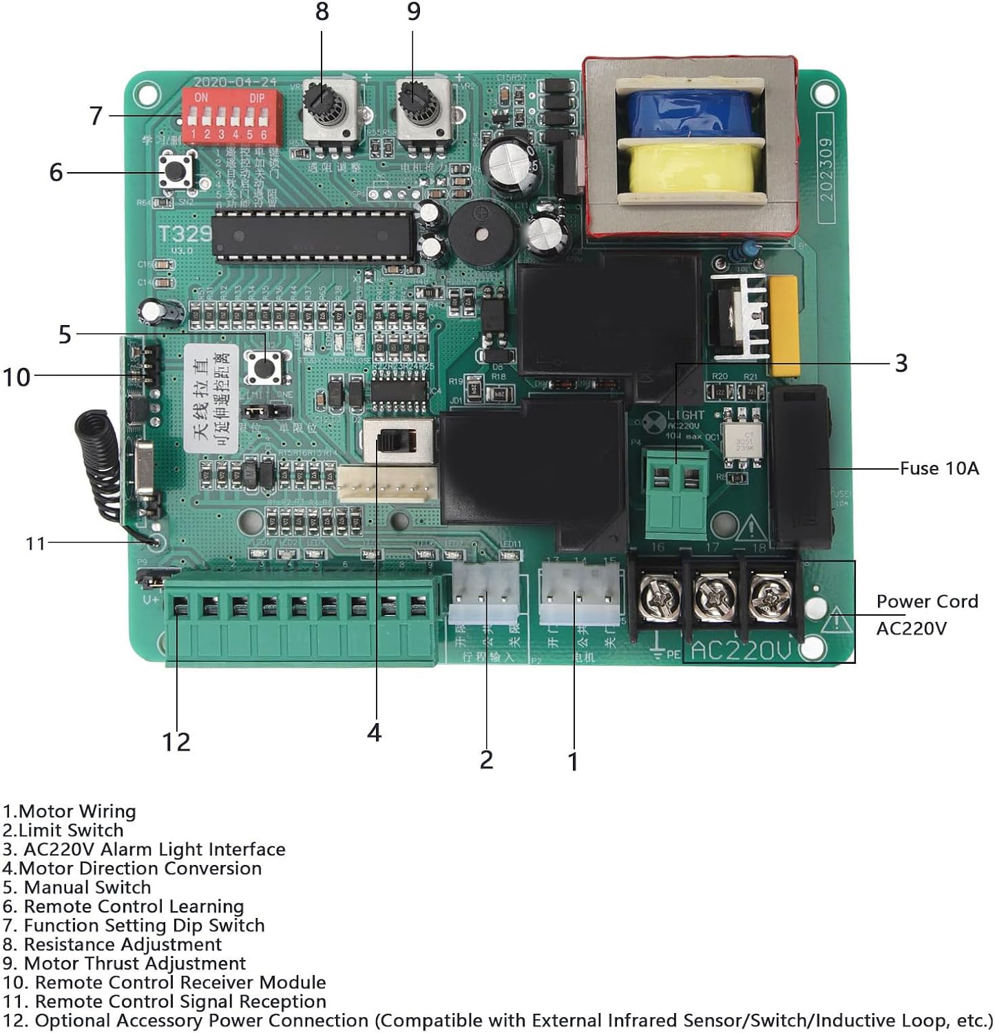
Image : Une image détaillée view of the Fockety PCB control board, highlighting key components with numbered labels for easy identification.
- Câblage du moteur : Terminals for connecting the gate motor.
- Fin de course: Connections for the gate's limit switches, which define the open and closed positions.
- AC220V Alarm Light Interface: Output for an external alarm light (220V).
- Motor Direction Conversion: Jumper or switch to reverse motor direction if needed.
- Interrupteur manuel : Terminals for connecting an external manual control switch.
- Remote Control Learning Button: Button used to program remote controls.
- Function Setting DIP Switch: A set of switches for configuring various operational parameters.
- Réglage de la résistance : Potentiometer for fine-tuning the motor's resistance sensitivity.
- Motor Thrust Adjustment: Potentiometer for adjusting the motor's force.
- Remote Control Receiver Module: Integrated module for receiving remote control signals.
- Remote Control Signal Reception Antenna: Antenna for optimal remote signal reception.
- Optional Accessory Power Connection: Terminals for connecting external accessories such as infrared sensors, additional switches, or inductive loops.
4. Installation
4.1 Connexions de câblage
Carefully follow the wiring diagrams for correct installation. Ensure all connections are secure and insulated.
4.1.1 Infrared Sensor Wiring
Connect infrared sensors to the designated terminals. Ensure the infrared sensor is set to a normally open (NO) interface.

Image: Diagram illustrating the correct wiring for infrared sensors to the control board, showing connections for GND, U+, and signal lines.
4.1.2 External Manual Switch Wiring
Connect an external manual switch for convenient gate operation. The diagram shows connections for Open, Stop, and Close functions.

Image: Diagram showing how to connect an external manual switch (e.g., a three-button switch for On/Stop/Off) to the control board's terminals.
4.2 Paramètres du commutateur DIP
The Function Setting DIP Switch (labeled 7 in the component diagram) allows configuration of various operational parameters. Refer to the specific DIP switch settings table (not provided in source, but implied by 'Function Setting Dip Switch') for detailed configuration options. Ensure power is off before adjusting DIP switches.
5. Fonctionnement
5.1 Apprentissage de la télécommande
- Press the Remote Control Learning Button (labeled 6) on the controller for 1 second.
- Release the button when the LED6 indicator turns off.
- Press and hold any button on the remote control without moving it.
- The LED indicator will flash three times to confirm successful learning. The remote control can now be used.
- Repeat this method for additional remote controls.
5.2 Suppression de la télécommande
- Press and hold the Remote Control Learning Button (labeled 6) for approximately 8 seconds.
- Release the button after hearing an audible prompt tone. This action will delete all programmed remote controls.
5.3 Motor Force and Speed Adjustment
- Motor Thrust Adjustment (labeled 9): Use the potentiometer to customize the motor's operating force. This allows for fine-tuning based on gate weight and movement requirements.
- Resistance Adjustment (labeled 8): Adjust this potentiometer to set the sensitivity for obstruction detection. When the gate encounters significant resistance during closing, it will automatically stop to prevent accidents or damage.
- Fonction de vitesse lente : The control board provides adjustable slow speed parameters for both opening and closing, ensuring smooth and stable gate operation.
5.4 One-Button Control
The system supports convenient one-button control for manual opening and closing, offering sensitive control and high anti-interference capabilities.
6. Entretien
The control board features LED indicators that provide clear visual feedback on motor operation and system status. These indicators are useful for quick debugging and routine maintenance checks.
- Inspectez régulièrement tous les branchements électriques afin de détecter tout signe d'usure ou de dommage.
- Keep the control board clean and free from dust and moisture.
- Periodically test the automatic stop function to ensure safety mechanisms are working correctly.
7. Dépannage
- Portail ne répondant pas : Check power supply, remote control battery, and ensure remote control is properly programmed. Verify all wiring connections.
- Arrêt inattendu de la porte : This may indicate the obstruction detection system has been triggered. Check for physical obstructions in the gate's path. Adjust the Resistance Adjustment potentiometer (labeled 8) if the sensitivity is too high.
- Incorrect Gate Direction: Use the Motor Direction Conversion jumper/switch (labeled 4) to reverse the motor's direction.
- Problèmes de télécommande : If a remote control is not working, try reprogramming it using the Remote Control Learning procedure. If multiple remotes are not working, consider performing a Remote Control Deletion and reprogramming all remotes.
- Indicateurs LED : Observe the LED indicators for diagnostic feedback. Consult a professional if the issue persists after basic troubleshooting.
8. Spécifications
| Fonctionnalité | Détail |
|---|---|
| Numéro de modèle | Fockety46vkhxczmi-11 |
| Vol d'entréetage | 220 V |
| Type de produit | Sliding Gate Opener PCB Control Board |
| Produit applicable | Moteur pour portail coulissant |
| Matériel | Composant électronique |
| Taille du produit | Approx. 130 x 108 mm / 5.1 x 4.3 inches |
| Poids | Environ 316 g / 11.1 oz |
| Piles incluses | Non |
| Piles requises | Non |

Image : Vue de dessus view of the control board, illustrating its compact size of approximately 130x108mm.
9. Garantie et assistance
9.1 Informations sur la garantie
This Fockety Sliding Gate Opener PCB Control Board comes with a 24-month warranty or refund policy, ensuring quality and customer satisfaction. Please retain your proof of purchase for warranty claims.
9.2 Assistance clientèle
For technical assistance, troubleshooting beyond this manual, or warranty inquiries, please contact the seller or authorized service provider. Provide your product model number (Fockety46vkhxczmi-11) and a detailed description of the issue when seeking support.