1. Introduction
This manual provides comprehensive instructions for the assembly, installation, operation, and maintenance of your RIVECO 12U 19-inch Wall Mount Server Rack. Please read this manual thoroughly before installation and retain it for future reference. This rack is designed to securely house standard 19-inch rack-mountable equipment such as network switches, patch panels, servers, and AV components.

Image 1.1: The RIVECO 12U 19-inch Wall Mount Server Rack, an open-frame design for efficient equipment mounting.
2. Consignes de sécurité
- Capacité de poids : Ne pas dépasser la charge maximale admissible de 80 kg (180 lb). Une surcharge peut entraîner une instabilité et des dommages.
- Montage mural : Ensure the mounting surface is structurally sound and capable of supporting the rack's weight plus the weight of all installed equipment. Use appropriate fasteners for your wall type (e.g., wood studs, concrete, drywall).
- Assemblée: Assemble the rack on a flat, stable surface. Wear appropriate personal protective equipment, such as gloves, to prevent cuts or pinches during assembly.
- Installation d'équipement: Distribute equipment weight evenly within the rack to maintain balance. Install heavier equipment at the bottom of the rack.
- Ventilation: The open-frame design promotes airflow. Ensure adequate space around the rack for proper ventilation of installed equipment.
3. Contenu du colis
Vérifiez que tous les composants sont présents avant de commencer l'assemblage :
- Steel frames (Top, Bottom, Side Rails)
- M6 Screws & Cage Nuts (1 pack)
- M6 Screws & Flange Nuts (1 pack)
- Bolts * 4 (for wall mounting)
If any parts are missing or damaged, please contact RIVECO customer support.
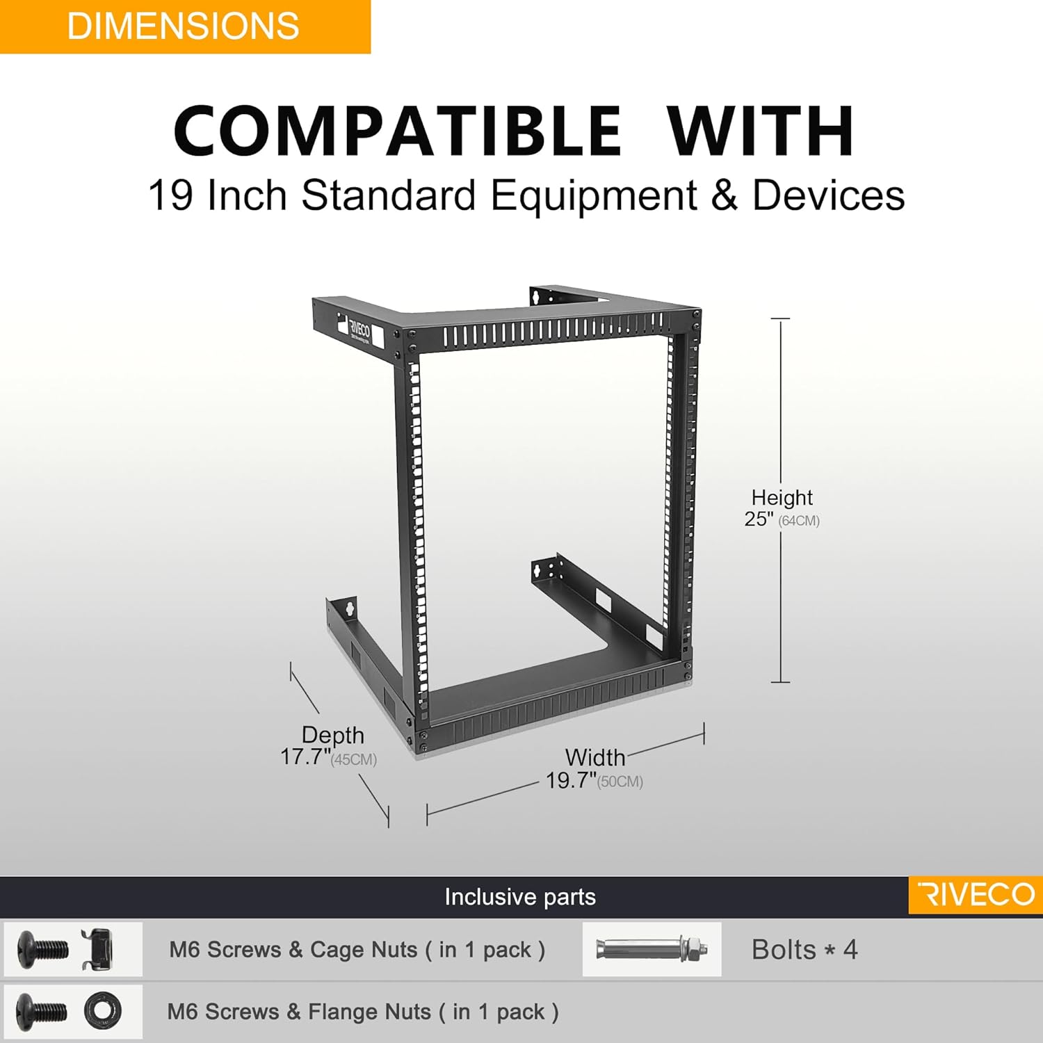
Image 3.1: Diagram showing the dimensions of the 12U rack and the included M6 screws, cage nuts, flange nuts, and wall mounting bolts.
4. Spécifications du produit
| Fonctionnalité | Spécification |
|---|---|
| Numéro de modèle | WF5412 |
| Unités de rack | 12U |
| Matériel | SPCC Cold-Rolled Steel (2.0mm thick) |
| Finition | Black RAL9005 Powder Coat (0.2mm thick) |
| Dimensions (L x P x H) | 17.7 po x 19.7 po x 25.1 po (45 cm x 50 cm x 64 cm) |
| Capacité de poids | 180 livres (80 kg) |
| Poids de l'article | 13.37 livres |
| Compatibilité | EIA-standard 19-inch rack equipment |
| Side Cage Nut Hole Distance | 470 mm |
5. Configuration et installation
5.1 Instructions de montage
- Déballer les composants : Retirez soigneusement toutes les pièces de l'emballage et vérifiez-les par rapport à la liste du contenu de l'emballage.
- Assemblage du cadre : Attach the side rails to the integrated top and bottom frames using the provided M6 screws and flange nuts. Ensure all connections are secure. The design features integrated top and bottom frames for structural integrity.

Image 5.1: Illustration of the rack's structural engineering, highlighting the integrated top and bottom frames for robust assembly.

Image 5.2: Detail showing the stable construction achieved by securing the frame components with screws.
5.2 Montage mural
- Sélectionnez l'emplacement: Choose a wall location that is structurally sound and can support the total weight of the rack and equipment. Consider accessibility for cabling and maintenance.
- Marquer les points de montage : Hold the assembled rack against the wall at the desired height. Use a pencil to mark the locations for the wall retaining holes. Ensure the marks are level and align with wall studs if possible (standard stud spacing is often 16 inches).
- Percer des trous pilotes : Drill pilot holes at the marked locations. The size of the drill bit will depend on the type of wall fasteners being used.
- Install Wall Anchors (if needed): If mounting into drywall without studs, install appropriate heavy-duty wall anchors (not always included, may require separate purchase).
- Support de montage : Align the rack's wall retaining holes with the drilled holes/anchors. Secure the rack to the wall using the provided bolts or suitable heavy-duty fasteners. Ensure the rack is firmly attached and stable before proceeding.

Image 5.3: Diagram illustrating the use of a wall retaining hole for secure mounting, showing a bolt installed inside the wall.
5.3 Installation de l'équipement
- Installer les écrous cage : For equipment requiring cage nuts, insert the M6 cage nuts into the square holes on the rack rails at the desired unit (U) positions. The rack rails are numbered for easy unit identification.
- Équipement de montage : Align your 19-inch rack-mountable equipment with the installed cage nuts. Use the provided M6 screws to secure the equipment to the rack. Ensure all equipment is securely fastened.
- Gestion des câbles: Utilize the open frame design for efficient cable routing. Consider using cable ties or management panels (sold separately) to organize cables and maintain airflow.

Image 5.4 : Gros plan view of the numbered unit (U) markings on the rack rail, indicating installation locations for equipment.

Image 5.5: A RIVECO 9U rack (similar to 12U model) shown mounted on a wall with various network and AV equipment installed, demonstrating its load capacity and versatility.
6. Mode d'emploi
The RIVECO Wall Mount Server Rack is a passive component designed to house and organize your equipment. Proper operation primarily involves ensuring equipment is correctly installed and maintained.
- Equipment Loading: When adding or removing equipment, ensure the rack remains stable. It is recommended to install heavier items towards the bottom of the rack to maintain a low center of gravity.
- Gestion des câbles: Regularly inspect and manage cables to prevent tangles, improve airflow, and reduce strain on connectors.
- Débit d'air : The open frame design facilitates natural convection. Avoid blocking the front, back, or sides of the rack with obstructions that could impede airflow to your equipment.

Image 6.1: A RIVECO rack with a power strip, network switch, and other components installed, illustrating a typical setup.
7. Entretien
Regular maintenance ensures the longevity and safe operation of your RIVECO Wall Mount Server Rack.
- Nettoyage: Periodically wipe down the rack with a soft, dry cloth to remove dust. For stubborn dirt, a slightly damp Un chiffon peut être utilisé, suivi d'un séchage immédiat. Évitez les nettoyants abrasifs ou les solvants.
- Vérification des fixations : Annually, or as needed, inspect all assembly screws and wall mounting bolts. Tighten any loose fasteners to ensure the rack remains stable and secure.
- Inspection structurelle : Check the steel frames for any signs of bending, cracks, or corrosion. Address any issues promptly to prevent structural compromise. The black powder coat finish is designed to resist scratching and rusting.
8. Dépannage
This section addresses common issues you might encounter with your server rack.
- Rack Instability After Mounting:
- Problème: The rack feels wobbly or not securely attached to the wall.
- Solution: Re-check all wall mounting bolts. Ensure they are fully tightened and that the wall anchors (if used) are appropriate for the wall material and weight. If mounting into drywall, consider locating wall studs for a more secure installation or using heavy-duty toggle bolts.
- Equipment Not Fitting:
- Problème: 19-inch equipment does not align with the rack holes or is too deep.
- Solution: Verify that your equipment is indeed 19-inch rack-mountable. Ensure the cage nuts are correctly inserted into the square holes. The rack has a depth of 17.7 inches; ensure your devices are no longer than 17.5 inches to fit properly.
- Difficulty Inserting Cage Nuts:
- Problème: Cage nuts are hard to insert or do not stay in place.
- Solution: Ensure you are using the correct M6 cage nuts. Insert one lip of the cage nut into the square hole, then use a cage nut tool (or a flathead screwdriver carefully) to push the other lip into place until it snaps securely.
9. Garantie et assistance
RIVECO products are manufactured to high-quality standards. For specific warranty information, please refer to the documentation provided at the time of purchase or contact RIVECO customer support.
If you encounter any issues with your RIVECO 12U 19-inch Wall Mount Server Rack, or if you have questions regarding assembly, installation, or operation, please contact RIVECO customer support for assistance. Please have your model number (WF5412) and purchase information ready when contacting support.