1. Introduction
This user manual provides detailed instructions for the installation, operation, and maintenance of the AMOCAM K80 Power Supply Control unit. This device is designed to provide stable DC 12V power for various door access control systems, including electric locks, access controllers, and exit buttons. Please read this manual thoroughly before installation and use to ensure proper function and safety.
2. Consignes de sécurité
- Assurez-vous que le volume d'entréetage (AC 110-240V) matches the specifications before connecting.
- All wiring should be performed by a qualified electrician to prevent electrical shock or damage.
- Coupez l'alimentation électrique avant toute installation, maintenance ou dépannage.
- N’exposez pas l’appareil à l’humidité ou à des températures extrêmes.
- Cet appareil est destiné à être utilisé en intérieur uniquement.
- Assurez-vous d'une bonne mise à la terre pour éviter les risques électriques.
3. caractéristiques du produit
- Vol d'entrée universeltage: Supports AC 100-240V, 50-60Hz, suitable for various regions.
- Sortie stable : Provides stable DC 12V, 3A output for connected devices.
- Contrôle polyvalent : Features NC (Normally Closed) and NO (Normally Open) outputs to control various electric locks (e.g., electric gate lock, strike lock, bolt lock, magnetic lock).
- Adjustable Lock Delay: Integrated delay control circuit allows adjustment of lock time from 0 to 15 seconds.
- Protections de sécurité : Includes short-circuit and overload protection.
- Conception compacte : Petit et léger pour une installation facile.
- Large application : Compatible with building intercoms, villa doorbells, apartment doorphones, home video door phone controllers, and various access control systems.
4. Spécifications
| Modèle | K80 (Item Model Number: 12V-Powers) |
| Vol d'entréetage | AC 110-240V, 50-60Hz |
| Volume de sortietage | DC 12V, 3A |
| Lock Delay Time | Réglable 0-15 secondes |
| Dimensions (L x l x H) | 5.5 x 3.7 x 1.5 pouces (140 x 94 x 38 mm environ) |
| Poids de l'article | 11.1 onces (315 grammes) |
| Fabricant | AMOCAM |
| Code UPC | 647726600253 |
5. Configuration et installation
Before beginning installation, ensure all power is disconnected. The AMOCAM K80 Power Supply Control unit is designed for easy integration into existing or new access control systems.
5.1 Identification des composants

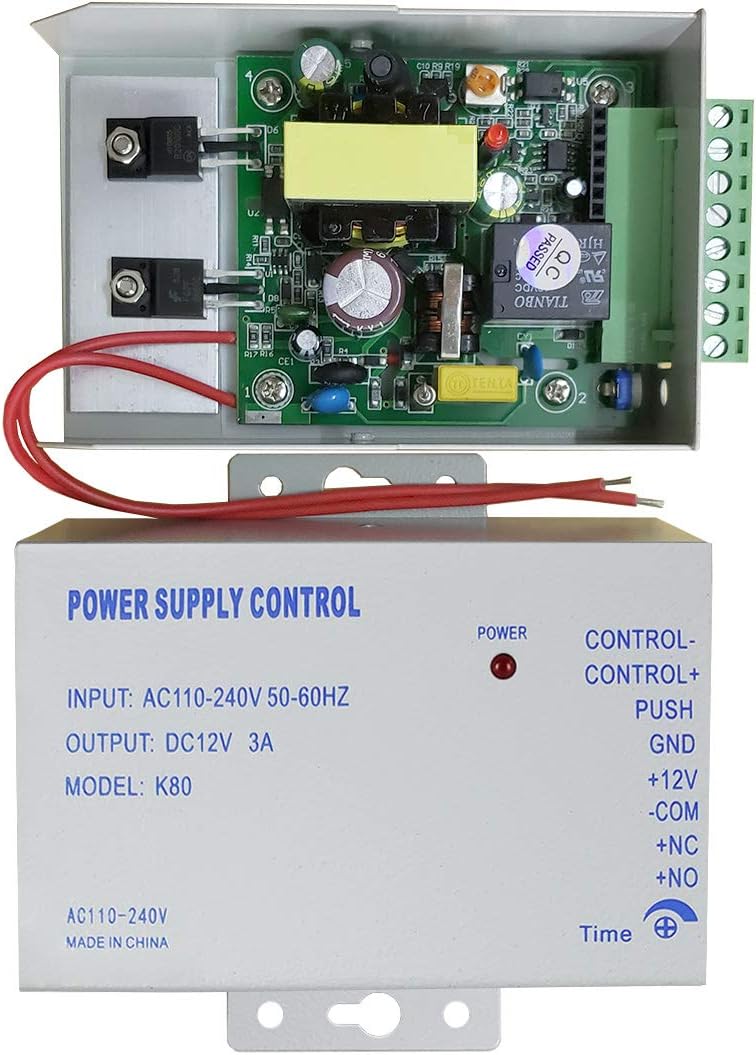
The unit features clearly labeled terminals for input power, control signals, and output to electric locks. A red LED indicates power status.
5.2 Schémas de câblage
Refer to the following diagrams for correct wiring configurations.
5.2.1 AC Input Wiring

Connect the AC 110-240V power source to the designated AC input terminals on the K80 unit. It is recommended to connect through a circuit breaker for safety.
5.2.2 Access Control System Wiring
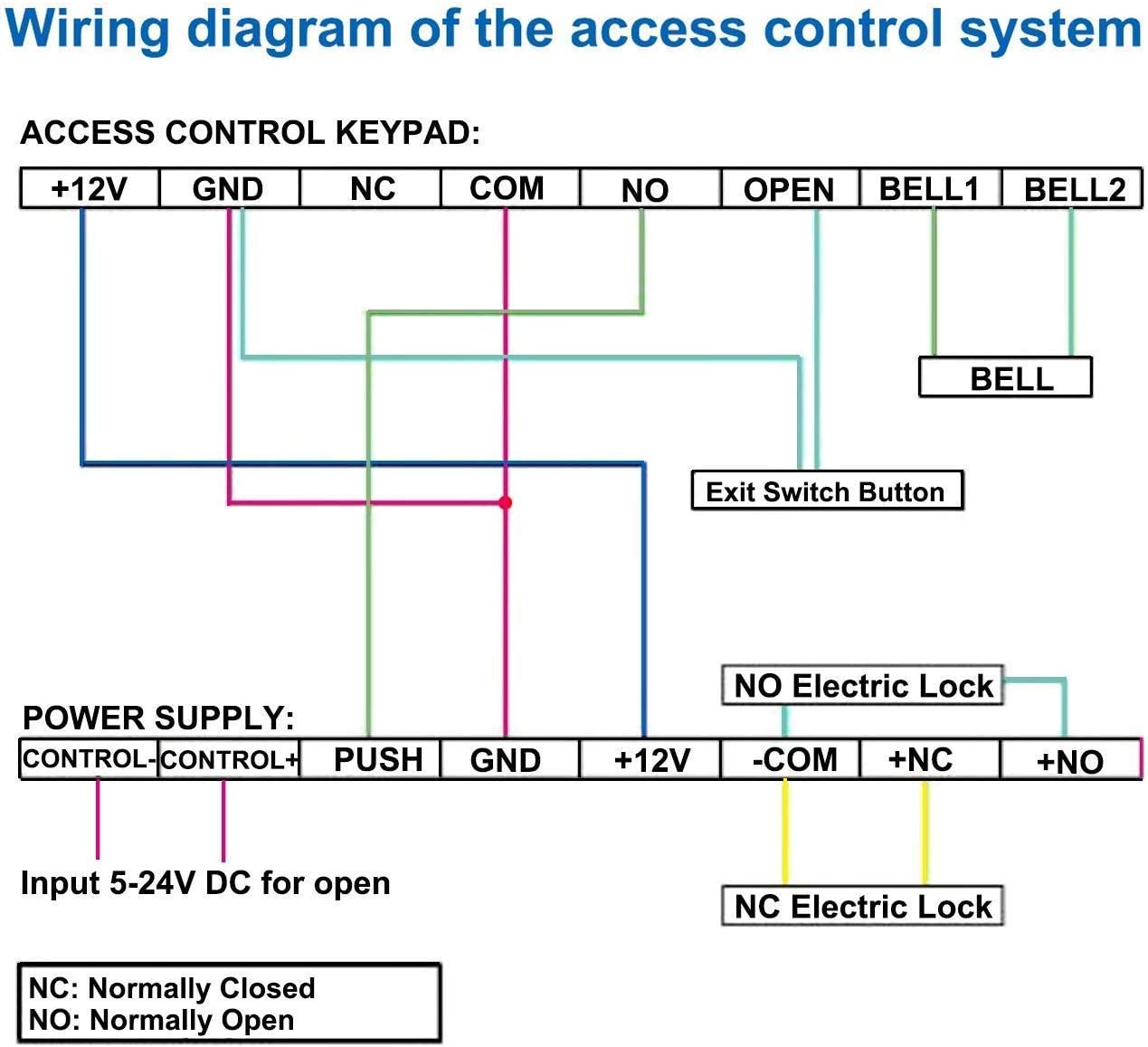

The K80 unit provides terminals for:
- CONTROL- / CONTROL+: Input for 5-24V DC to trigger the lock release.
- POUSSER: Connects to an exit button.
- GND : Connexion à la terre.
- +12V : DC 12V output for powering devices like keypads or doorbells.
- -COM: Common terminal for lock connections.
- +NC: Normally Closed output for electric locks (lock is closed when power is off).
- +NO: Normally Open output for electric locks (lock is open when power is off).
Ensure all connections are secure and correctly matched to the corresponding terminals on your access control devices and electric locks.
6. Fonctionnement
6.1 Mise sous tension
Once all wiring is complete and verified, connect the AC power. The red "POWER" indicator LED on the K80 unit should illuminate, indicating that the unit is receiving power and providing DC 12V output.
6.2 Adjusting Lock Delay Time

The K80 unit features an adjustable dial for setting the lock release delay time. This dial is typically located on the side or bottom of the unit and can be adjusted using a small screwdriver. The delay can be set from 0 to 15 seconds, allowing the connected electric lock to remain open for the desired duration after activation.
- To adjust, locate the "Time" dial.
- Use a small screwdriver to carefully turn the dial to increase or decrease the delay.
- Test the lock operation after adjustment to ensure the desired delay is achieved.
6.3 Lock Control
The K80 unit controls electric locks via its NC and NO outputs.
- Normally Closed (NC) Locks: These locks remain locked when power is applied and unlock when power is interrupted. Connect to the +NC and -COM terminals.
- Normally Open (NO) Locks: These locks remain unlocked when power is applied and lock when power is interrupted. Connect to the +NO and -COM terminals.
When an access control device (e.g., keypad, exit button) sends a signal to the K80 unit, it will momentarily cut or apply power to the connected lock terminals based on the lock type (NC/NO) and the set delay time, thereby releasing or securing the lock.
7. Entretien
- Nettoyage: Use a dry, soft cloth to clean the exterior of the unit. Do not use liquid cleaners or solvents.
- Inspection: Vérifiez régulièrement tous les branchements électriques pour vous assurer qu'ils sont bien fixés et exempts de corrosion.
- Conditions environnementales : Ensure the unit is kept in a dry environment, away from direct sunlight and extreme temperatures.
- Aucune pièce réparable par l'utilisateur : The internal components are not user-serviceable. Do not attempt to open or repair the unit yourself, as this will void the warranty and may cause electrical hazards.
8. Dépannage
| Problème | Cause possible | Solution |
|---|---|---|
| Aucun voyant d'alimentation (LED rouge éteinte) | No AC input power; faulty wiring; internal fuse blown. |
|
| Electric lock does not open/close | Incorrect lock wiring (NC/NO); faulty lock; insufficient power; incorrect delay setting. |
|
| Lock opens/closes too quickly/slowly | Incorrect lock delay time setting. | Adjust the "Time" dial on the K80 unit to the desired delay (0-15 seconds). |
| L'unité semble chaude | Overload; poor ventilation. |
|
9. Garantie et assistance
For warranty information or technical support, please contact AMOCAM customer service. Refer to your purchase documentation for specific warranty terms.
AMOCAM Technology Inc. is committed to providing high-quality products and customer support.