![]()
HM-30 Pump Panel Module
Installation Guide

17600 SW 65th Ave, Lake Oswego, OR 97035 USA
800-527-0555 · firecom.com
HM-30 Pump Panel Module Installation Guide
Tools Needed
- Crimp tool for RJ12 connectors (not included, part# 108-0023-00)
- ½ inch drill bit for CA Cable (not included)
- Drill (not included)
- Screwdriver with #2 Phillips bit (not included)
- #29 drill bit or 1/8 inch bit is acceptable (not included)
Contents
- HM-30 module
- 75′ of 6c flat cable (installed)
- RJ connector (installed)
- 2 spare RJ connectors
- Installation Guide

HM-30 Module Installation Steps
- Observe the location desired to mount the module.
Note: Use caution of location that is being drilled as to not damage anything behind the metal. - Reference the diagrams for the HM-30 dimensions and mark the mounting screw locations on your installation surface. Also, mark the location of the CA cable hole.
- Drill pilot holes for the mounting screws with the #29 drill bit (1/8 inch size bit acceptable) and also drill a 1/2 inch pilot hole at the same time for the CA cable.
- Secure HM-30 module with provided screws to pump panel.
- Route HM-30 flat CA Cable to the Firecom intercom.
- Plug the RJ12 connector into the desired intercom port on the back of the Firecom intercom.
HM-30 Diagrams


Modular Plug Installation Steps
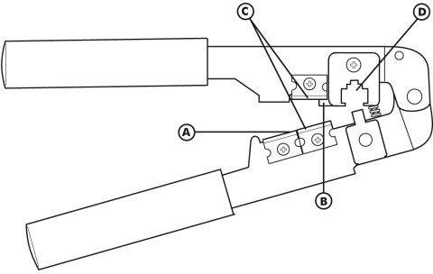
- Using the cutter blade on the crimping tool (A), cut the flat CA Cable so the cut is clean and 90 degrees to the sides of the cable.
- Insert one end of the CA Cable between the stripping blades (C) until the end of the cable hits the stop (B).
- Squeeze the handles of the crimping tool together until the tool bottoms out.
- While holding the handles together, pull the cable out of the tool.
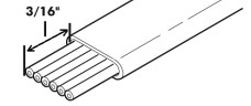
- The stripped insulation should expose approximately 3/16″ of wire.
- Push a RJ Modular Plug into the plug holder on the crimping tool (D) until the release tab on the plug locks into position.
- Holding the cable so it’s orientated like in Figure 1 from the Wiring Diagram section below, push the cable into the plug as far as it will go.
- Squeeze the tool handles COMPLETELY together. You may feel the crimper finish punching the contacts through the insulation on the wires.
- Let the handles spring open.
- Push down on the release-tab on the RJ Modular Plug and remove the RJ Modular Plug from the crimping tool.
- Inspect the plug to ensure that the cable is held securely in place.
Wiring Diagram
In the event the modular plug is removed, please reference the diagram below:
 Figure 1
Page intentionally left blank
Firecom, a division of Sonetics Corporation
Copyright ©2020 Sonetics Corporation. All rights reserved.
The information in this document is subject to change without notice.
600-0090-00 Rev A
Documents / Resources
 | FIRECOM HM-30 Pump Panel Module [pdf] Installation Guide HM-30 Pump Panel Module, HM-30, Pump Panel Module |


