![]()

DIAB EP104
Quick Start Guide
EC Declaration of Conformity (original version)
Manufacturer
FAAC Nordic AB
Box 125. 284 22 Perstory. Sweden
Person authorized to compile the technical documentation
Ulf Ivarsson. FA.AC Nordic AB. Box 125. 284 22 Pesstorp. Sweden
General description and type designation
Automatic control unit for doors, gates, or barriers: EP104-1. EP104-2
We hereby declare that the EP104 ant0CnatiC control unit meets, the relevant requirements of Machinery Directive 2006/42/EC. EMC Directive 2014/30/EU. Low Voltage Directive 2014,–35. EL’. RoHS Directive 2011/65/ EL’ inclusive (EU)2015/863 and Construction Products Regulation EL’ 305;2011
The automatic control unit EP104-1. EP104-2 is. .-here applicable, compliant with the following harmonized standards:
- 55-EN 132414–A2:2016 Industrial. commercial and garage doors and barriers — Product standard. performance
- SS-EN 13849-1:2016 Safety-related pasts of control Is-stems — Past I General principles for design
- SS-EN 60335-1 Household and similar electrical appliances – Safer: – Part 1 General requirements.
- 55-EN 60335-2-103 Household and similar electrical appliances – Safety – Part 2-103: Particular requirements for drives for bacon, doors, and windows
- SS-EN 61000-6-2 Electromagnetic compatibility (EMC) – Part 6-2: Generic standards – Lcunanstiry for industrial
- $5-EN 61000-6-3 Electromagnetic compatibility EMC) – Pan 6-3: Genetic standards – Emission standard for residential, commercial and
This declaration relates to automatic control unit EP1-4-1. EP104-2 is specified in the condition in which it is placed on the market. and does not covet components added and,. or modifications made thereafter Nor does it relate to thud-parry equipment or to interfaces between thud-pasty equipment and the equipment specified below and supplied by FAAC Nordic AS The instruction manual/installation manual for automatic control runt EP104-1. EP104-2 must be followed and attention must be paid to risks in the installation of a door, gate, or barrier.
We declare that the EP104 does not contain- concentrations above 0.1°.. any substances specified in the REACH 190′ .2006 EC Candidate List of Substances of Very High Concern or banned substances in RoHS. 2011/65/EC.
Declaration of performance
Intended use of the construction product
Automatic control unit Intended for installation indoors. gates or barriers for use in industry, commercial areas, and residential areas that are open to the public. and intended to provide secure access for people. goods and vehicles
System for the assessment and continuous verification of the performance of the construction product System 3
Performance
| Property | Performance | Harmonized standard |
| Force exerted | SS-EN 13241 + A2:2016 | |
| Performance level e* | BS EN ISO 13849-1:2016 |
| Performance level d* | BS EN ISO 13849-1:2016 |
| ||
Perstorp, 12/06/2019
Ola Hansson CEO
These instructions are to be considered as a rapid guide for installation and to confirm the correct handing and polarity of the motors. They can also be used to confirm the
operating logic before additional safety devices are fitted to the system as specified by the Risk Assessment undertaken by the installer. The installer should still familiarise
themselves with the full manual and the safety information contained within.
(available at https://www.faac.se/data/pdf/instruction_manual_ep104_4_08_r4_en_with_sheet_c999.pdf)
Installation Sequence
- Perform a Risk Assessment for the system and resolve by design as many risks as possible
- Secure the card into a suitable enclosure, please note that a EP104-1 will only run 1 motor and a EP104-2 will run 2 motors or just 1 motor
- Mount the motors as detailed in their relevant instructions
- Use suitable cabling for the motors and accessories (Encoders should be wired in a separate duct to the motor supply cables and ideally a screened cable)
- Wire the electronic control board as per Page 3 and Page 4 for the power supply, motor, encoders, stop circuit, and photocell circuit
- Power up the EP104 Board
- Verify the status of the LED’s as per Page 6
- Wire in an Opening trigger as per Page 8 into Input 1
- Familiarise yourself with how to program the EP104 control board as per Page 5
- Begin Basic Programming of the EP104 on Page 6 and Page 7
- Provide an opening command to verify that the system works correctly, it should open and require another command to Input 2 to close again.
- If Automatic Closing is required, adjust parameter C500 as per Page 8. It should now form a closed position, open on Input 1 and when fully open the “Start” LED will begin to flash as it counts down the pause time and then automatically close (barring any permanent commands or safety circuits being breached
- Connect Safety Devices to the system as deemed required by the Risk Assessment carried out previously.
a. Hard Wired Safety Edges can be wired as per Page 7
b. Wireless Safety Edges can be connected via the same terminals as in “13-a” but the output of the Wireless Safety Edge system should be configured to output a resistive
circuit the BUS 2easy connection if using the FAAC XTR and XTS Wireless Receiver system
c. Traditional Photocells can be wired and configured as per Page 4
d. XGuard Laser Curtains would be configured as Traditional Photocells in 14.c - Connect any additional activation commands as per Page 8
- If using either Safety Edges or Inherent Obstacle Detection as a part of the Risk Assessment, there are useful Functions that can be modified to assist in attaining compliance on Page 40 of the main EP104 manual
- If using XGuard Laser Curtains, please test these in accordance with BS EN 12445/12453
- Hand over all relevant documentation to the end customer as required by the Technical File and the Supply of Machinery (Safety) Regulations 2008
EP104 Basic Power, Motor, and Encoder Wiring
Ensure that the EP104-1 or EP104-2 is in a suitable enclosure and ideally be in visual sight of the gate for commissioning purposes.
Fit the Gate Operator/s as per the drawings provided.
Power and Motor Connections
Connect the main power to the board and wire the motors in accordance with the power available on site and matching motor. 3-Phase power supply to the control board as required and shown below. Encoder, Stop, and Photocell Connections
Encoders
Connect the Encoders to the EP104 Board as shown below. Please ensure that the cable supplying the encoder is shielded or not sharing the conduit as the motor power supply. Stop Circuit
Link Terminal 7 to 12 if no emergency stop button is present, otherwise fit an N/C Emergency Stop Button across the terminals.
Photocell Circuit – Default Function is Active on Closing Only
Connect a Photocell as per the below or Link Terminal 28 to 29, you can also wire a Photocell into Input 6 as shown below and configure the Input to Safety in P600 = 2 for the safety device. (Page 51 of the main manual) Please note that by default P600 once set to safety device only functions on closing. If acting on opening is required, please set P640 = 0 and P642 = 1 for Reversal to Fully Closed.
Configuring the EP104
Before starting programming the EP104, it is best to familiarize yourself with navigating through the menus. The EP104 display can show a value up to 4 digits long, or a channel number with the prefix C, d, F, L, o, P, or r followed by 3 digits. If an E appears followed by a 3-digit number, this is an Error message (please refer to Error Messages in
the main manual on page 53). Please note that on the first power-up, the display will show EP-1 or EP-2 which is identifying if this is a unit design for one or two motors, respectively.
Please study the below, which explains the process.
| Display | Description | |
 | Channel number for the EP104 |  |
 | Channel number for the vehicle detector | |
 | Channel number for the frequency converter | |
 | Channel number for the limit switch | |
 | Channel number for the output card | |
 | Channel number for programmable inputs | |
 | Channel number for the wireless card | |
 | Error message (not EP-1 and EP-2) | |
 | Readout of value | |
 | Value being changed | |
| Button | Description | |
| + | Button to increase the channel or value | |
| – | Button to decrease the channel or value | |
| Switch between channel number and value | ||
| Save /confirm the changed value | ||
| Switch between different channel groups | ||
- Readout of parameters in the EP104
Press the button so the display shows the channel number – a letter followed by digits.
Press the button to quickly change between letters (channel groups).
Press the +or – button to step to the channel number you want.
Press the show the value on the display
Press thebutton again to exit and return to the channel number. Leave the unit in this mode – you cannot exit any further - Setting parameters in the EP104
Select the channel number according to the readout above.
Press the button. The vale starts flashing and is ready to be changed.
Press the + or – button to step to the vale you want.
Press thebutton to save the vale.
Press thebutton again to exit and return to the channel number. Leave the unit in this mode – you cannot exit any further
EP104 – First Steps
Step 1
First navigate to C999 and change the value to “0” (this allows display of all registers).
Ensure that Photo/Safe/Stop/24V are all illuminated Green. To check motor rotation and encoders, we first put the EP104 into Service Mode. In this mode only the internal Open/Stop/Close buttons are functional. It should come default in this mode.
Set CO33 = 5
Step 2 — Main Power Settings
Set Power type in C202 to “0” for 3-Phase 400V with Neutral, or “2” for Single Phase with Neutral (Asymmetric).
Step 3 — Checking Motor Direction
To test the operation of the motor as we are in Service Mode, set L001= 4 and set L002 = 0, this will allow movement of only Motor 1. If you are using an EP104-1, please disregard L002.
At this point, you should be able to use the Dead-Man Controls on the board itself (The three buttons below the display, 1″ Black is the Open, 2″ Black is Close) to move the gate in the desired direction. If the gate moves in the opposite direction to the button being pressed, you need to switch the motor polarity as shown in the Power and Motor Connections section above or double-check L110 = 1 (Motor 1 on the left as viewed from inside) or 2 (Motor 1 on the right as viewed from inside). If you are using an EP104-2, repeat the process but set L001 = 0 and set L002 = 4 and perform the same test but now double-check L120 = 1 (Motor 2 on the left as viewed from inside) or 2 (Motor 2 on the right as viewed from inside). Please only press the button for a second or so to check movement as otherwise, it is most likely that an error will be generated, as have not yet set the power readings.
If it does not move, something is not wired correctly, check incoming voltage, motor connections first.
Step 4 – Motor Power and Encoder Settings
We can now adjust the power and encoder settings of the EP104. If you have a Single Leaf system, please skip to (14). At this stage, the gates can be in any position, ideally halfway to start and engaged to the operator.
- Set L001= 0 and L002 = 4
- Set C240 =0
- C241 (Motor Power Readout), it should say 0.00 with the gate stopped. Press and hold the Open Button on the board and make a note of the value when the gate is moving and then press the Close Button on the board and make a note of the value when the gate is moving
- Set C242 = average value recorded from C241 when opening plus 0.3
- Set C243 = average value recorded from C241 when closing plus 0.3
- C261 (Motor Current Readout), it should say 0.00 with the gate stopped. Press and hold the Open Button on the board and make a note of the value when the gate is moving and then press the Close Button on the board and make a note of the value when the gate is moving
- Set C262 = average value recorded from C261 when opening
- Set C263 = average value recorded from C261 when closing
- Set L002 = 1
- Check L120 is set to either “1” if Motor 2 is on the Left or “2” if on the right (viewed from the motor side)
- L121 (Position Readout Motor 2). Press and hold the Open Button on the board until the gate is fully open and make a note of the value. Now press the Close Button on the board and make a note of the value
- Set L122 = value recorded from L121 when fully open
- Set L123 = value recorded from L121 when fully closed
- Set L002 = 0 and L001= 4
- Set C230 =0.0
- C231 (Motor Power Readout), it should say 0.00 with the gate stopped. Press and hold the Open Button on the board and make a note of the value when the gate is moving and then press the Close Button on the board and make a note of the value when the gate is moving
- Set C232 = average value recorded from C231 when opening plus 0.3
- Set C233 = average value recorded from C231 when closing plus 0.3
- C251 (Motor Current Readout), it should say 0.00 with the gate stopped. Press and hold the Open Button on the board and make a note of the value when the gate is moving and then press the Close Button on the board and make a note of the value when the gate is moving
- Set C252 = average value recorded from C261 when opening
- Set C253 = average value recorded from C261 when closing
- Set L001= 1
- Check L110 is set to either “1” if Motor 1 is on the Left or “2” if on the right (viewed from the motor side)
- L111 (Position Readout Motor 1). Press and hold the Open Button on the board until the gate is fully open and make a note of the value. Now press the Close Button on the board and make a note of the value
- Set L112 = value recorded from L111 when fully open
- Set L113 = value recorded from L111 when fully closed
- Set L002 = 1
At this stage, while the EP104 is in Service Mode, the Internal Open and Close Buttons will operate the gate/s in Dead-Man Operation within the encoder settings set above.
Step 5 – Safety Edge Circuit
Wire in Safety Edges as shown below. Please note that the External Unit for personal protection is representing an optional wireless Safety Edge Controller system.

If NO Safety edges are to be connected to the control board, please adjust the following parameters accordingly otherwise it will not function correctly. (Page 36, 37)
NO SE.C1 Edge (Closing) —C111 = 0 (adjust to 2 if required) NO SE.C2 Edge (Closing) —C121 = 0 (adjust to 2 if required) NO SE.01 Edge (Opening)— C131 = 0 (adjust to 2 if required) NO SE.O2 Edge (opening)— C141 = 0 (adjust to 2 if required)
Step 6 – Take the EP104 out of Service Mode
Set CO33 = 3. In this mode, the gate will function from the internal buttons and will operate in a single press to Open fully with the Open Button and a single press to Close fully with the Close Button and all safeties active.
EP104 – Inputs and Automatic Closing
Inputs
The EP104-1 has 6 different inputs, as shown below.

Partial Openings
If only 1 gate is required to open in a double gate system from time to time, we would normally suggest using Input 3. The following settings will need to be adjusted to make it function in this method.
Set P360 = 1
Set P362 = 1
In this method, only Motor 1 will open fully and close if automatic closing is enabled. If P362 is set to “2” then only Motor 2 will open fully and close if automatic closing is enabled.
If you would like to enable the partial opening of Motor 1 or/and Motor 2 from time to time, we would normally suggest using Input 4 (if Input 3 is already in use above). The following settings will need to be adjusted to make it function in this method.
Set P460 = 1
Set P462 = 1 if applicable to Motor 1 only, 2 if applicable to Motor 2 only or 3 if applicable to both Motors Set P463 = 1
Set L116 = degree position where Motor 1 will stop (use L111 to see the reading in normal operation)
Set L126 = degree position where Motor 2 will stop (use L121 to see the reading in normal operation)
Automatic Closing
By default, the EP104 operates by using Input Commands as shown in the diagram above and it is in a Pulse to Open and Pulse to Close function. If Automatic Closing is required, please set the parameter below.
Set C500 = Automatic Closing time 0(minutes).00(seconds), i.e. 20 seconds pause time = 0.20
If you would like to set the Parking Logic function whereby the Closing Safety Photocell will trigger a command to close once activated and then cleared. You can also set a delay as per below from the Photocell trigger.
Set C351 = 1
Set C354 = 1 to close immediately or 2 to close only once the gate is fully open
Set C510 = Delay before automatic closing 00(seconds), i.e. 20 seconds pause time = 20
EP104 – Outputs and Connecting a Lock
Outputs
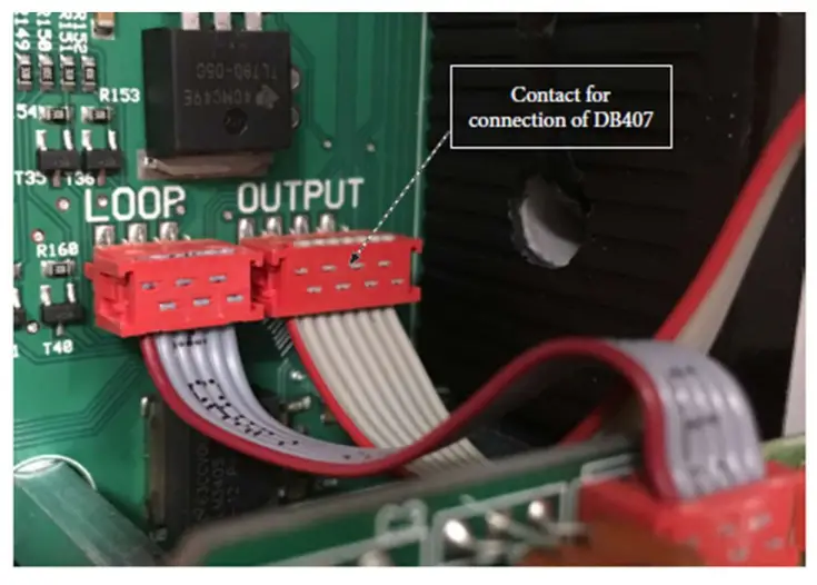
The EP104 does not have any outputs natively. If the output is required to control traffic lights, control locks or provide position indicators to a BMS on-site, then the use of a DB407 Output Card is required. Please note that if you are replacing a version 4.06 or below EP104, you will also require a new DB407 as the current control boards are not
compatible with the older versions of the DB401 (the original version of the output card). The DB407 is connected to the EP104 and wired as shown below.
Please ensure that the EP104 is completely powered down before installation of the output card and that the desired outputs are wired in as per the below, and then power the EP104 back on.

In general terms, the DB407 is used to both connect a Magnetic Lock to the gate and/or connect a traffic light system.
Wiring a Magnetic Lock to an EP104
When it is being used to connect a Magnetic lock, we would recommend the use of o2 and i1 and run a separate power supply positive to the Magnetic Lock through the Output 2 relay (shown in the next page). This Output is already pre-configured to be enabled in the closed position and disabled as soon as the gate gets a command to open.

Wiring a Traffic Light to a EP104
When it is being used to connect a Traffic Light, we would recommend the use of o5 and o6 and i3 and run a separate power supply positive to the Traffic Light and you would switch the negative through the outputs as per below. Magnetic Lock through Output 2 relay (shown in the next page). The following settings will need to be adjusted to make it function in this method.
Set o500 = 1
Set o511 = 1
Set o512 = 1
Set o513 = 3
Set o600 = 1
Set o610 = 1

Common Errors and Troubleshooting
Error code | Meaning | Possible cause |
| EP-1 | Not an error code — indicates the mile of EP1O4 in use | |
| EP-2 | Not an error code — indicates the type of EP104 in use | |
| E017 | Safety edge or load guard triggered five times in succession | It something preventing the door from relating to the closed position? |
| E020 | Vo page too high in Safety circuit | The voltage measured by the automated control unit is too high. |
| E021 | Vantage too low in the safety circuit | Check eternal safety circuit |
| E 02 5 | The incorrect setting for personal protection, motor 1 | Check COO and 0230, the load guard cannot be disabled with personal protection activated. Cheek 0211, it cannot be longer than 006 seconds. C212 cannot be longer than ‘ seconds. C493 cannot be longer than 0.20 seconds. |
| E.026 | The incorrect setting for personal protection, motor 2 | Check COO and C240, the load guard cannot be disabled with personal protection activated. Cheek C211, it cannot ti be longer than 006 seconds. C21_ be longer than seconds. 0493 cannot be longer than 0.20 seconds. |
| E027 | The incorrect setting for motor protection, low limit inactive | If CO2 is not set to 4 C301 may not be set to 1. C201 is only used with a frequency converter. |
| E201 | Motor protection triggered for motor 1 | The motor is taking more than 1 5x motor current Motor is sluggish or stops. Pithy fuse? Phase failure in an incoming phase? Break-in cable to motor oc motor winding? Check the motor protection setting |
| E202 | Motor protection triggered for motor 2 | |
| E203 | Motor protection triggered four times in a /M control unit locked for 3 minutes | Is there an obstacle? Fault in an electric motor?’ Check the configuration of channels C252, C253, Ca C263. |
| E8204 | Current through motor 1, which is switched off | |
| E205 | Current through motor 2, which is switched off | |
| E236 | No current or low current in motor 1 | The electric motor is running at less than half the motor protection setting Check the motor protection setting Phase future in an incoming phase? Faulty fuse? Break-in the cable to the electric motor? Voltage drop in stop circuit/limit switch circuit? |
| E207 | No current or low current in motor 2 | |
| B221 | Sort load too low motor 1 | Check that the motor is correctly connected. |
| E222 | Check that the motor is correctly connected. | |
| Son load too lot motor 2 | ||
| E223 | Normal power too low, motor 1 | Cheek 00. |
| E224 | Normal power too low motor 2 | Check C240. |
| Ez25 | The load guard has been nipped three times in a row | The obstacle in the way? Is mechanical fault preventing dosing? Check the load guard settings. |
| E931 | Stop at the same time as an open/close operation | |
| E932 | Open operation at the same time as a close operation. | |
| E941 | Motor 1 running in the wrong direction according to the encoder setting | Check that channel L120 is set to the correct side. Check the motor is owning in the right direction. |
| E942 | Motor 2 running in the wrong direction according to the encoder setting | Check that channel L120 is set to the correct side. Check the motor is running in the right direction. |
| E943 | No morena encoder 1 | Check connection to the encoder |
| E944 | No movement encode: 2 | Check connection to the encoder |
Troubleshooting
Problem | Possible cause, tip |
| Error message in the display (Enna) | See the section above on error messages. |
| The door reverses and the red LEDs Ill /352 start flashing | Is the load guard correctly installed? Has the correct supply voltage been set? Mechanical fault? Does the door move easily when decoupled? |
| Axe the red LEDs SEC I, SEC:, SEO1 or 3E02 on or filter | Check the channels for the safety edge value. Is the impedance correct? Adjust the safety edge switch if necessary? Are all the safety edge units in use? Are any of the limit switch IEDs on? The safety edge will not work unless the limit switches are connected at the time the power is switched on. Is the stop L.ED on? The safety edge will not work unless the stop circuit is uninterrupted at the time the power is switched on. |
| The door sr.la not open or close. | Are all the green LEDs that should be lit on? Have unused: top inputs been jumpered? Are any of the LEDs DIPILNP6 on? They should not usually be on (unless the system .s parked at certain times). The limit switch LEDs must light ..–..p before the door can be operated. Example: LOX is on = motor I can start. The limit switches are connected in series with the stop circuit. huh/interruption in the wicket door contact or another contact in the stop circuit. Check that the warnings are configured. Check that the block is configured. |
![]()
Documents / Resources
 | FAAC DAAB EP104 Automatic Control Unit [pdf] User Guide DAAB EP104, Automatic Control Unit, DAAB EP104 Automatic Control Unit |


