1. Introducción
The ETCR2000A Digital Clamp Ground Resistance Tester is a specialized instrument designed for measuring grounding resistance in various electrical systems. This device offers a non-intrusive method for testing loop resistance without the need to disconnect grounding leads or use auxiliary electrodes, making it suitable for applications in power systems, meteorology, oilfields, construction, and industrial electrical equipment.
It accurately measures the combined resistance of the grounding body and lead, and is capable of detecting ground faults that traditional methods may miss. This manual provides detailed instructions for the safe and effective use of your ETCR2000A tester.
2. Información de seguridad
ADVERTENCIA: Lea todas las advertencias e instrucciones de seguridad antes de usar este producto. El incumplimiento de las advertencias e instrucciones podría provocar una descarga eléctrica, un incendio o lesiones graves.
- Always observe local and national safety regulations.
- Do not use the instrument if it appears damaged or operates abnormally.
- Ensure the instrument is clean and dry before use.
- No exceda los valores máximos de entrada para ninguna función.
- Always disconnect the instrument from the circuit before opening the battery compartment.
- This device is designed to measure loop resistance only, not single-point grounding. For single-point grounding, an artificial loop must be created.
3. Contenido del paquete
Verifique que todos los elementos enumerados a continuación estén presentes y en buenas condiciones:
- ETCR2000A Digital Clamp Ground Resistance Meter
- Anillo de prueba
- Manual de usuario
- LR6 Battery (AA, 1.5V) x 4
- Estuche de transporte

Image: The ETCR2000A kit, showing the clamp meter, test ring, user manual, batteries, and protective carrying case.
4. Producto terminadoview
The ETCR2000A features an intuitive design for ease of use. Familiarize yourself with the main components:

Imagen: Frente view of the ETCR2000A, showing the display, clamp jaws, and control buttons.

Imagen: Lateral view of the ETCR2000A, illustrating the clamp opening mechanism and the jaw size.

Image: Close-up of the clamp jaws, highlighting the internal voltage and current coils for measurement.

Image: Key features of the ETCR2000A, including its resistance range, resolution, clamp jaw size, and data memory capacity.
5. Configuración
5.1 Instalación de la batería
- Asegúrese de que el dispositivo esté apagado.
- Localice el compartimiento de la batería en la parte posterior de la unidad.
- Utilice un destornillador para abrir la tapa del compartimento de la batería.
- Insert four LR6 (AA, 1.5V) batteries, observing the correct polarity (+/-).
- Vuelva a colocar la tapa del compartimiento de la batería y asegúrela con el tornillo.
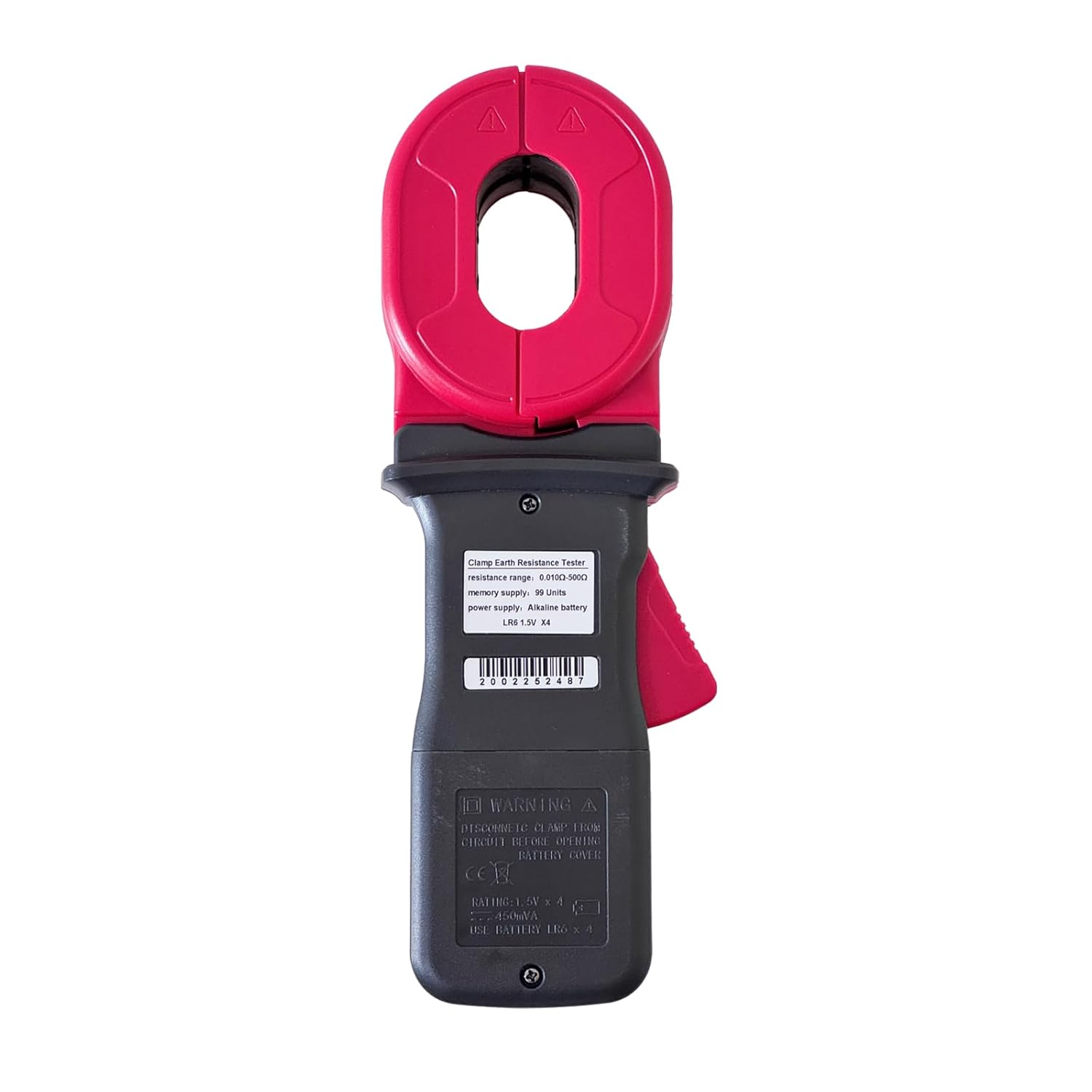
Imagen: Trasera view of the ETCR2000A, indicating the location of the battery compartment.
6. Instrucciones de funcionamiento
6.1 Encendido / Apagado
Presione el FUERZA Botón para encender o apagar el dispositivo.
6.2 Taking a Measurement (Loop Resistance)
The ETCR2000A is designed for loop resistance measurement. It measures induced potential and current to calculate resistance using the formula R=E/I.
- Ensure the circuit to be tested forms a closed loop. The tester cannot measure single-point grounding directly. If testing a single grounding electrode, an artificial loop must be created (e.g., by connecting a temporary conductor to another known ground point or using the provided test ring).
- Abre la clamp mandíbulas presionando la palanca.
- Coloque el clamp around the grounding conductor or loop to be measured. Ensure the jaws are fully closed and there are no gaps.
- El valor de resistencia se mostrará en la pantalla LCD.
- For stable readings, hold the clamp steady during measurement.
6.3 Función de retención de datos
Presione el SOSTENER Botón para congelar la lectura actual en la pantalla. Presiónelo de nuevo para liberar la función de retención.
Selección de 6.4 modos
El MODO button may be used to cycle through different measurement modes or display options if available. Refer to the on-screen indicators.

Image: The ETCR2000A display showing 'OL' (Open Loop), which indicates the circuit is not closed or the resistance is out of range.
7. Mantenimiento
7.1 Limpieza
Wipe the instrument with a dry, soft cloth. Do not use abrasive cleaners or solvents. Ensure no moisture enters the device.
7.2 Reemplazo de batería
Cuando aparezca el indicador de batería baja en la pantalla, reemplace las baterías como se describe en la sección 'Instalación de la batería' (5.1).
7.3 Almacenamiento
Store the instrument in its carrying case in a cool, dry place, away from direct sunlight and extreme temperatures. Remove batteries if the device will not be used for an extended period.
8. Solución de problemas
| Problema | Posible causa | Solución |
|---|---|---|
| Sin pantalla o pantalla débil | Baterías agotadas o bajas | Reemplace las baterías. |
| "OL" (Open Loop) displayed | Circuit is not a closed loop; clamp jaws not fully closed; resistance is out of range. | Ensure the circuit forms a complete loop. Check that the clamp jaws are fully closed around the conductor. Verify the resistance is within the 0.010Ω-500Ω range. |
| Lecturas inexactas | Interference; dirty clamp jaws; improper contact. | Move away from strong electromagnetic fields. Clean the clamp jaws. Ensure good contact with the conductor. |
9. Especificaciones
| Parámetro | Valor |
|---|---|
| Modelo | ETCR2000A |
| Rango de resistencia | 0.010 Ω - 500 Ω |
| Resolución de resistencia | 0.001 Ω |
| Clamp Tamaño de la mandíbula | 55 mm x 32 mm |
| Tamaño de apertura | 32 mm |
| Fuente de poder | 4 x LR6 (AA) 1.5V Batteries |
| Vol. Mínimo de funcionamientotage | 6 voltios (CC) |
| Clasificación de temperatura superior | 55°C |
| Peso del artículo | 2.1 libras (aprox. 0.95 kg) |
| Dimensiones del artículo | 10.83 x 3.94 x 2.2 pulgadas (aprox. 27.5 x 10 x 5.6 cm) |
| Tipo de medida | Ohmmeter (Loop Resistance) |
| Especificación cumplida | CE |
| Datos de memoria | 99 Grupos |
9.1 Precisión
The ETCR2000A provides precise measurements. For the 50.0-99.5 Ohm range, the accuracy is typically ±1.5% + 0.5 Ohms. Accuracy may vary slightly across different ranges. Always ensure proper calibration and environmental conditions for optimal performance.
10. Aplicaciones
The ETCR2000A is suitable for a wide range of professional applications:
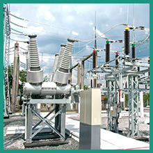
Image: Testing in power substations.

Image: Use on construction sites.

Image: Testing telecommunication towers.
11. Garantía y soporte
For warranty information and technical support, please refer to the documentation provided with your purchase or contact ETCR customer service. Keep your purchase receipt as proof of purchase.