1. Introducción
Thank you for choosing the AstroAI AM33D or DM200M Digital Multimeter. This manual provides essential information for the safe and effective operation, maintenance, and troubleshooting of your device. Please read this manual thoroughly before use and retain it for future reference.
1.1 Información de seguridad
Always adhere to basic safety precautions when using electrical testing equipment to reduce the risk of fire, electric shock, or personal injury. This device is designed for safe operation when used according to these instructions.
- Lee todas las instrucciones: Understand the functions and limitations of the multimeter before operation.
- Use appropriate range: Always select the correct measurement range to avoid damage to the meter or the circuit being tested.
- Inspect test leads: Before each use, check test leads for damaged insulation or exposed metal. Replace if damaged.
- Do not exceed maximum input values: Refer to the specifications section for maximum voltage y calificaciones actuales.
- Evite las condiciones húmedas: Do not operate the multimeter in wet environments.
- Ensure proper fuse protection: The multimeters are equipped with ceramic fuses to protect against burning and overloading. Do not bypass or use incorrect fuses.
- Desconectar la energía: Desconecte siempre la alimentación del circuito antes de conectar o desconectar los cables de prueba, especialmente al medir corriente.
- Beware of live circuits: Tenga mucho cuidado al trabajar con circuitos activos.
2. Producto terminadoview y características
The AstroAI AM33D and DM200M are versatile digital multimeters designed for accurate measurement of various electrical parameters. They are suitable for household, automotive, and general electrical troubleshooting.

Figura 2.1: AstroAI DM200M Digital Multimeter with included test leads and a 9V battery. This image displays the main unit, red and black test probes, and a standard 9V battery, illustrating the complete package.
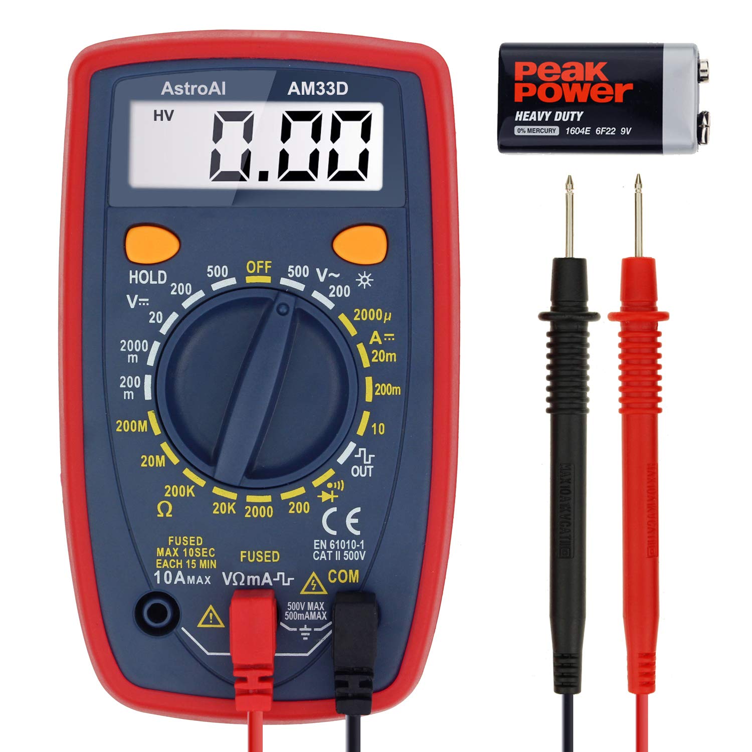
Figura 2.2: AstroAI AM33D Digital Multimeter with included test leads and a 9V battery. This image shows the AM33D model, its test probes, and a 9V battery, highlighting the components.
2.1 Características principales
- Medidas versátiles: Mide con precisión el volumen de CA/CCtage, DC Current, Resistance, and Diode. The DM200M also includes Non-Contact VoltagDetección de velocidad de conducción nerviosa (NCV).
- Diseño fácil de usar: Features data hold, max value recording, 15-minute auto power off, and a low battery indicator.
- Legibilidad mejorada: Backlit display and flashlight (DM200M) for easy troubleshooting in dimly lit areas.
- Portátil y compacto: Designed for easy transport and storage, fitting into toolboxes or glove compartments.
- Características de seguridad: Equipped with two ceramic fuses to protect against burning and overloading. Includes a silicone protective case and a kickstand for convenience.
3. Configuración
3.1 Instalación de la batería
The multimeters typically use a 9V battery. To install or replace the battery:
- Asegúrese de que el multímetro esté apagado y desconecte todos los cables de prueba.
- Localice la tapa del compartimiento de la batería en la parte posterior de la unidad.
- Desatornille el/los tornillo(s) de retención y retire la cubierta.
- Inserte una batería nueva de 9 V, observando la polaridad correcta (+ y -).
- Vuelva a colocar la tapa del compartimiento de la batería y fíjela con el/los tornillo(s).
3.2 Conexión de cables de prueba
Conecte siempre los cables de prueba correctamente para obtener mediciones precisas y seguras.
- Insertar el negro cable de prueba en el COM (común) jack.
- Para la mayoría de los volúmenestage, resistance, and diode measurements, insert the rojo cable de prueba en el VΩmA Jacobo.
- Para mediciones de corriente (hasta 10 A), inserte el rojo cable de prueba en el 10A Jacobo.
- For smaller current measurements (up to 200mA/250mA), insert the rojo cable de prueba en el VΩmA Jacobo.
4. Instrucciones de funcionamiento
This section details how to perform various measurements using your AstroAI digital multimeter.
4.1 Funcionamiento general
- Interruptor giratorio: Gire el interruptor giratorio a la función y rango de medición deseados.
- Botón ESPERA: Presione para congelar la lectura actual en la pantalla. Presione nuevamente para liberarla.
- MAX Button (DM200M): Press to display the maximum measured value. Press again to exit.
- FUNC Button (DM200M): Used to switch between different functions within a single rotary switch position (e.g., AC/DC, Diode/Continuity).
- Backlight Button (DM200M): Press to turn on the display backlight. Press again to turn off.
4.2 Vol. CAtagMedición electrónica
Para medir el voltaje CAtage:
- Coloque el interruptor giratorio en la posición 'V~' (Volumen de CA)tage) rango. Seleccione un rango apropiado mayor que el volumen esperado.tage.
- Conecte los cables de prueba al circuito en paralelo con la carga.
- Leer el vol.tage valor en la pantalla.

Figura 4.1: The AM33D multimeter measuring AC voltage from a standard wall outlet. The display shows '110', indicating 110V AC. Note: The meter cannot be used to test AC current when the dial is set to AC voltage.
4.3 Vol. CCtagMedición electrónica
Para medir DC voltage:
- Set the rotary switch to the 'V--' (DC Voltage) rango. Seleccione un rango apropiado mayor que el volumen esperado.tage.
- Conecte el cable de prueba rojo al lado positivo (+) del circuito y el cable de prueba negro al lado negativo (-).
- Leer el vol.tage valor en la pantalla.

Figura 4.2: The AM33D multimeter measuring DC voltage from a 9V battery. The display shows '9.69', indicating 9.69V DC.

Figura 4.3: The DM200M multimeter measuring DC voltage from a 9V battery. This image demonstrates the DM200M's capability for DC voltagy medición.
4.4 Medición de corriente continua
Para medir la corriente continua:
- IMPORTANTE: Disconnect power to the circuit before connecting the multimeter.
- Set the rotary switch to the 'A--' (DC Current) range. Select an appropriate range.
- Connect the multimeter in series with the circuit. For currents up to 10A, use the 10A jack for the red lead. For smaller currents, use the VΩmA jack.
- Aplique energía al circuito y lea el valor actual en la pantalla.

Figura 4.4: The DM200M multimeter measuring DC current in a car battery circuit. The display shows '0.68', indicating 0.68A DC. This illustrates how to measure current in series.
4.5 Medición de resistencia
Para medir la resistencia:
- Asegúrese de que el circuito esté completamente desenergizado antes de medir la resistencia.
- Coloque el interruptor giratorio en el rango 'Ω' (Resistencia).
- Conecte los cables de prueba al componente cuya resistencia desea medir.
- Lea el valor de resistencia en la pantalla.
4.6 Prueba de diodos y prueba de continuidad
To perform a diode test or continuity test:
- Asegúrese de que el circuito esté desenergizado.
- Set the rotary switch to the Diode/Continuity symbol. Use the FUNC button on DM200M to toggle between functions if needed.
- Para la prueba de diodos: Conecte el cable rojo al ánodo y el cable negro al cátodo. La pantalla mostrará la tensión directa.tagCaída electrónica. Invierta los cables para comprobar si hay circuito abierto.
- For Continuity Test: Connect the test leads across the component. A low resistance (typically below 50Ω) will indicate continuity, often accompanied by an audible beep.
4.7 vol. sin contactotage (NCV) Detection (DM200M Only)
The DM200M model features NCV detection for identifying live AC voltagy sin contacto directo.
- Coloque el interruptor giratorio en la posición 'NCV'.
- Mueva el extremo superior del multímetro cerca del conductor o toma de corriente.
- The multimeter will emit an audible beep and/or flash an indicator light if AC voltagSe detecta e.

Figura 4.5: The DM200M multimeter being used for versatile circuit troubleshooting in an engine bay. The image highlights various functions like AC/DC Voltage, Resistance, NCV, Data Hold, and Max Value, demonstrating its broad application.
4.8 Backlit Display (DM200M Only)
The DM200M features an easy-to-read backlit display for use in low-light conditions.

Figura 4.6: The DM200M multimeter displaying a clear, backlit reading. The image also provides an internal view, illustrating the placement of the 250mA and 10A ceramic fuses for enhanced safety.
5. Mantenimiento
5.1 Reemplazo de fusibles
The multimeters are protected by internal ceramic fuses. If the current measurement function stops working, the fuse may need replacement.
- Asegúrese de que el multímetro esté apagado y desconecte todos los cables de prueba.
- Abra la tapa del compartimiento de la batería (consulte la Sección 3.1).
- Retire con cuidado la parte trasera casing of the multimeter to access the circuit board and fuses.
- Identify the blown fuse(s). The DM200M typically has a 250mA/250V fuse and a 10A/250V fuse. The AM33D has a 500mA/500V and a 10A/500V fuse.
- Replace the blown fuse(s) with new fuses of the exact same type and rating. Using incorrect fuses can compromise safety and damage the meter.
- Reassemble the multimeter, ensuring all screws are securely fastened.
5.2 Limpieza
Para limpiar el multímetro, limpie la carcasa con un paño.amp Paño y detergente suave. No utilice abrasivos ni disolventes. Asegúrese de que el dispositivo esté completamente seco antes de usarlo.
6. Solución de problemas
- Sin pantalla o pantalla tenue: Check the battery. Replace if low.
- Lecturas incorrectas: Ensure test leads are properly connected, the correct function/range is selected, and the circuit is de-energized for resistance/continuity tests.
- La medición actual no funciona: Check and replace the appropriate fuse (refer to Section 5.1).
- Indicador de batería baja: A battery symbol on the display indicates that the battery voltage es bajo y necesita reemplazo.
7. Especificaciones
| Parámetro | Valor |
|---|---|
| Marca | AstroAI |
| Números de modelo | AM33D, DM200M |
| Mostrar recuentos | 2000 cuentas |
| Tipo de medida | Multimeter (AC/DC Voltage, DC Current, Resistance, Diode) |
| Additional Functions (DM200M) | NCV, Backlight, Max Value Recording |
| Fuente de poder | Battery Powered (9V battery, typically) |
| Safety Rating (DM200M) | CAT III 600 V |
| Safety Rating (AM33D) | CATII 500V |
| Apagado automático | 15 minutos (aprox.) |
| Fuses (DM200M) | 250mA/250V, 10A/250V Ceramic Fuses |
| Fuses (AM33D) | 500mA/500V, 10A/500V Ceramic Fuses |
8. Garantía y soporte
AstroAI provides a limited warranty for its products. For specific warranty details, claims, or technical support, please refer to the warranty card included with your product or visit the official AstroAI webSitio. No intente reparar el dispositivo usted mismo, ya que esto podría anular la garantía y representar riesgos de seguridad.