1. Información importante de seguridad
Please read this user manual thoroughly before operating the DEWIN Variable Frequency Drive (VFD). Failure to follow instructions may result in electrical shock, equipment damage, or personal injury. Keep this manual for future reference.
- Peligro de descarga eléctrica: Este dispositivo funciona con alto volumen.tage. Only qualified personnel should perform installation, wiring, and maintenance.
- Desconexión de energía: Always disconnect all power sources before servicing the VFD. Wait at least 10 minutes after removing power to allow capacitors to discharge before touching any components.
- Puesta a tierra adecuada: Ensure the VFD is properly grounded according to local electrical codes.
- Condiciones ambientales: Install the VFD in a clean, dry, and well-ventilated area, free from dust, corrosive gases, and excessive humidity.

2. Producto terminadoview
The DEWIN Variable Frequency Drive (VFD) is designed to convert single-phase 220V input into three-phase 220V output, allowing for precise speed control of three-phase motors. It features a unique control method for high torque, high precision, and a wide speed range.
2.1 Características principales
- Integrated Radiator: Equipped with a radiator for efficient heat dissipation, ensuring stable long-term operation.
- Unique Control Method: Achieves high torque, high precision, and a wide speed range.
- Fácil de usar: Compact size, easy to install, quick start/stop response, and significant torque at low speeds.
- Rendimiento alto: Excellent anti-aging and anti-snap performance, adaptable to sudden power changes, temperature, humidity, and dust interference, enhancing stability.
- Nine-Fold Protection: Incluye protección contra sobrevoltaje.tage, bajo volumentage, overcurrent, overload, overtemperature, power module faults, ground faults, short circuits, and motor stall.

2.2 Componentes del panel de control
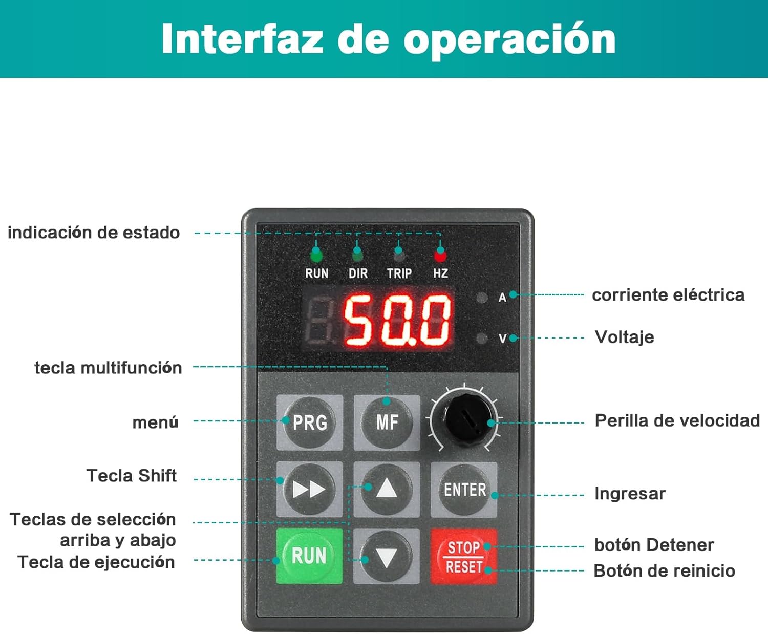
The control panel is designed for intuitive operation and can be detached for easier wiring and installation via screw terminals.

3. Configuración y cableado
Proper wiring is crucial for the safe and correct operation of the VFD. Ensure all power is disconnected before proceeding with any wiring.
3.1 Basic Power and Motor Wiring
Connect the single-phase 220V AC input to terminals L1 and L2. Connect the ground wire to the ground terminal. Connect the three-phase motor to output terminals U, V, and W.


3.2 Detailed Control Wiring
The VFD offers various control input and output terminals for advanced functionality, including multi-speed control, analog frequency commands, and fault indications.

3.3 Conexión de la resistencia de frenado
The VFD is equipped with an integrated braking resistor. If an external braking resistor is required for applications with high inertia loads or frequent braking, connect it to the P and PB terminals.

4. Instrucciones de funcionamiento
This section describes the basic operation of the VFD using the control panel.
4.1 Encendido y pantalla inicial
After connecting power, the VFD's digital display will illuminate, showing the current operating status or a default frequency. The status indicators (RUN, DIR, TRIP, HZ) will provide visual feedback.
Ajuste de velocidad 4.2
The VFD allows for continuous speed regulation from 0 to 999Hz, providing precise control over motor speed.
- Using the Speed Knob: Rotate the speed knob on the control panel to adjust the output frequency and, consequently, the motor speed. Turning clockwise increases speed, counter-clockwise decreases it.
- Digital Adjustment: For precise frequency settings, use the PRG (Menu) button to enter parameter settings, then use the Up/Down keys and ENTER button to modify the frequency parameter. Refer to the detailed parameter list in the full manual for specific parameter codes.

4.3 Start and Stop Operation
- Comenzar: Presione el CORRER button to start the motor. The RUN indicator will illuminate.
- Stop: Presione el PARADA REPOSICIÓN button to stop the motor. The RUN indicator will turn off.
- Reset: If a fault occurs and the TRIP indicator is lit, pressing the PARADA REPOSICIÓN button will clear the fault and reset the VFD.
5. Mantenimiento
Regular maintenance ensures the longevity and reliable operation of your DEWIN VFD.
- Limpieza: Keep the VFD clean and free from dust. Use a soft, dry cloth for cleaning. Do not use liquid cleaners.
- Ventilación: Ensure proper airflow around the VFD. The integrated radiator requires unobstructed ventilation to dissipate heat effectively.
- Comprobaciones de conexión: Periodically inspect all wiring connections for tightness and signs of wear or corrosion. Loose connections can lead to poor performance or damage.
- Monitoreo ambiental: Asegúrese de que el entorno operativo permanezca dentro de los rangos de temperatura y humedad especificados para evitar daños.
6. Solución de problemas
Esta sección ofrece orientación general para problemas comunes. Para problemas complejos, consulte a un técnico cualificado.
- VFD Not Powering On: Revise la fuente de alimentación de entrada y asegúrese de que todas las conexiones estén seguras. Verifique que el disyuntor o el fusible no estén disparados.
- El motor no funciona: Ensure the VFD is receiving a RUN command. Check motor wiring for correct phase sequence and secure connections. Verify the frequency setting is not 0Hz.
- TRIP Indicator On: This indicates a fault. Press the PARADA REPOSICIÓN button to clear the fault. If the fault persists, identify the fault code displayed (if any) and refer to the full manual's fault code section for specific causes and remedies. Common faults include overcurrent, overvoltage, y sobrecarga.
- Abnormal Motor Noise or Vibration: Check motor parameters in the VFD settings. Ensure the motor is properly mounted and balanced.
7. Especificaciones
| Característica | Especificación |
|---|---|
| Marca | DEWIN |
| Modelo | JLS-E-2S-0.75G |
| Potencia nominal | 0.75 kW |
| Vol de entradatage | 220V Single-phase |
| Vol de salidatage | 220V Three-phase |
| Dimensiones (L x An x Al) | 115 mm x 85 mm x 140 mm (aprox.) |
| Peso del artículo | 1.12 kilogramos |
| Rango de frecuencia | 0-999Hz (Continuous regulation) |
8. Garantía y soporte
For warranty information, please refer to the terms provided at the point of purchase or contact your seller. For technical support or further inquiries, please contact DEWIN customer service through their official channels.


