1. Introducción
The Acegmet JXM8000 is a True RMS (TRMS) digital multimeter designed for accurate and reliable electrical measurements. It features both automatic and manual ranging capabilities, allowing for versatile use in various applications. This manual provides essential information for the safe and effective operation, maintenance, and troubleshooting of your device.
2. Información de seguridad
Always adhere to safety precautions when using electrical testing equipment. Failure to do so may result in electric shock, injury, or damage to the multimeter or equipment under test.
- Protección contra sobrecarga: The multimeter is equipped with overload protection. When the input voltage is below 250V, the device automatically prevents burnout.
- Fuse Disconnect Function: In case of excessive current, the internal fuses will blow to protect the multimeter's internal circuitry. If a fuse blows, the screen will display "FUSE" and an alarm will sound.
- Wrong Polarity Alarm: If the test leads are connected to ports that do not match the selected measurement function (gear position), the screen will display "LEAD" and emit an audible beep. Correct the lead connection immediately.
- Ensure the multimeter's safety class (IEC61010 CAT.600V CAT IV, 1000V CAT.III) is appropriate for the measurement task.
- No intente medir el vol.tages o corrientes que excedan los límites máximos especificados.
- Inspeccione los cables de prueba para detectar posibles daños antes de cada uso. Reemplace los cables dañados inmediatamente.
- No opere el multímetro si parece dañado o no funciona correctamente.
3. Producto terminadoview
The Acegmet JXM8000 Digital Multimeter features a robust design with a clear display and intuitive controls.
3.1 Componentes y controles
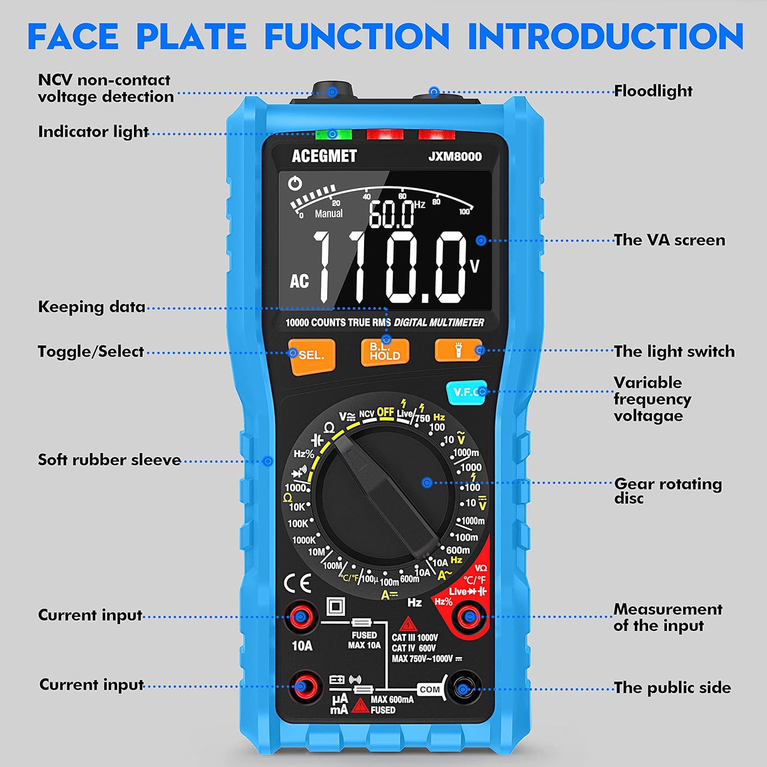
Figura 3.1: Frente view of the Acegmet JXM8000 Digital Multimeter with labeled components.
- VA Screen: Large LCD display for measurement readings, units, and indicators.
- Luz indicadora: Provides visual feedback for certain functions, such as NCV.
- Flash: Located at the top, activated by the light switch for illumination in dark areas.
- SEL. Button (Toggle/Select): Se utiliza para cambiar entre diferentes modos de medición dentro de una sola posición del interruptor giratorio (por ejemplo, CA/CC, Diodo/Continuidad).
- HOLD Button (Keeping Data): Congela la lectura actual en la pantalla. Presione de nuevo para liberarla.
- V.F.C Button (Variable Frequency Voltagmi): Activates the Variable Frequency Control measurement mode.
- Gear Rotating Disc: The central rotary switch used to select the desired measurement function.
- Tomas de entrada: Ports for connecting test leads. These include common (COM), voltage/resistance/frequency/capacitance (VΩHznF), and current (mA/10A) inputs.
- Soft Rubber Sleeve: A protective outer casing designed to prevent accidental electric shock and provide durability.
3.2 Características principales
- Verdadero valor eficaz (TRMS): Mide con precisión el volumen de CAtage and current for non-sine wave signals.
- Rango automático/manual: Offers flexibility for both automatic range selection and manual range control.
- Vol sin contactotagDetección de e (NCV): Detecta el volumen de CAtagy sin contacto físico.
- Live Line Test: Identifica cables activos.
- Medida de temperatura: Measures temperature in both Celsius and Fahrenheit.
- Pantalla de 10000 cuentas: Proporciona lecturas de alta resolución.
- Retención de datos: Congela la medición mostrada.
- Apagado automático: Se apaga automáticamente después de 15 minutos de inactividad para conservar la vida útil de la batería.
- Indicación de batería baja: Alertas cuando es necesario reemplazar las baterías.
4. Configuración
4.1 Instalación de la batería
The multimeter requires 2 x AA 1.5V batteries. To install or replace batteries:
- Asegúrese de que el multímetro esté apagado y los cables de prueba estén desconectados.
- Carefully remove the soft rubber sleeve.
- Localice la tapa del compartimiento de la batería en la parte posterior del dispositivo.
- Desatornille el/los tornillo(s) de retención y retire la cubierta.
- Insert the 2 x AA batteries, observing correct polarity (+/-).
- Vuelva a colocar la tapa del compartimiento de la batería y fíjela con el/los tornillo(s).
- Reinstall the soft rubber sleeve.
4.2 Conexión de cables de prueba
Always connect the black test lead to the "COM" (Common) jack. Connect the red test lead to the appropriate input jack based on the desired measurement:
- para vol.tage, Resistance, Frequency, Capacitance, Diode, and Continuity measurements, connect the red lead to the "VΩHznF" jack.
- For Current measurements (up to 600mA), connect the red lead to the "mA" jack.
- For High Current measurements (up to 10A), connect the red lead to the "10A" jack.
Ensure test leads are fully inserted into the jacks before taking measurements.
5. Instrucciones de funcionamiento
5.1 Encendido y apagado
To power on the multimeter, rotate the gear rotating disc from the "OFF" position to any desired measurement function. To power off, rotate the disc back to the "OFF" position.
5.2 Automatic and Manual Ranging

Figure 5.1: Rotary switch indicating Automatic and Manual Ranging sections.
- Función de rango automático: When the rotary switch is set to the "AUTOMATIC RANGE" section, the multimeter automatically selects the appropriate measurement range for AC/DC voltage, resistance, capacitance, frequency, on/off (continuity), and diode tests. This simplifies operation.
- Manual Range Function: When the rotary switch is set to the "MANUAL RANGE" section, you can manually select specific ranges for NCV, Live wire identification, AC/DC voltage, AC/DC current, temperature, and resistance measurements. This provides greater control for experienced users.
5.3 Medidas específicas
Siga estos pasos generales para la mayoría de las mediciones:
- Connect test leads correctly as described in Section 4.2.
- Rotate the gear rotating disc to the desired measurement function.
- If multiple functions are available at one position (e.g., AC/DC voltage), press the "SEL." button to toggle between them.
- Aplique los cables de prueba al circuito o componente bajo prueba.
- Read the measurement value on the VA screen.
5.3.1 VoltagMedición electrónica (CA/CC)
Set the rotary switch to the 'V' (Voltage) position. Use the 'SEL.' button to switch between AC (~) and DC ( ) voltage. Connect test leads in parallel with the circuit or component.
5.3.2 Medición de corriente (CA/CC)
Set the rotary switch to the 'A' (Current) position. Use the 'SEL.' button to switch between AC (~) and DC ( ) current. Connect test leads in series with the circuit. Ensure the correct input jack (mA or 10A) is used.
5.3.3 Medición de resistencia (Ω)
Set the rotary switch to the 'Ω' (Resistance) position. Connect test leads across the component. Ensure the circuit is de-energized before measuring resistance.
5.3.4 Prueba de continuidad
Set the rotary switch to the 'Ω' (Resistance) position and press 'SEL.' until the continuity symbol ( ) is displayed. A continuous beep indicates a low-resistance path (continuity).
5.3.5 Prueba de diodos
Set the rotary switch to the 'Ω' (Resistance) position and press 'SEL.' until the diode symbol ( ) is displayed. Connect the red lead to the anode and the black lead to the cathode of the diode. The forward voltagSe mostrará la gota.
5.3.6 Capacitance Measurement (nF/µF/mF)
Set the rotary switch to the 'nF' (Capacitance) position. Connect test leads across the capacitor. Ensure the capacitor is discharged before testing.
5.3.7 Medición de frecuencia (Hz)
Set the rotary switch to the 'Hz' (Frequency) position. Connect test leads to the signal source.
5.3.8 Medición de temperatura (°C/°F)

Figure 5.2: Multimeter demonstrating NCV, Live Line, and Temperature testing functions.
Set the rotary switch to the '°C/°F' (Temperature) position. Connect the included K-type thermocouple probe to the input jacks (usually VΩHznF and COM). Place the probe tip on or near the object whose temperature is to be measured. Press 'SEL.' to switch between Celsius and Fahrenheit.
5.3.9 vol. sin contactotagDetección de e (NCV)
Set the rotary switch to the 'NCV' position. Move the top of the multimeter near an AC voltage source. The indicator light will flash, and an audible beep will sound, with the frequency of beeps increasing as the multimeter gets closer to the voltagy fuente.
5.3.10 Live Line Test
Set the rotary switch to the 'Live' position. Insert the red test lead into the 'VΩHznF' jack. Touch the red test lead to the conductor to be tested. The display will indicate 'LIVE' and an audible alarm will sound if a live wire is detected.
5.4 Función de retención de datos
Pulse el botón "HOLD" para congelar la lectura actual en la pantalla. Vuelva a pulsarlo para desactivar la función de retención y reanudar las lecturas en tiempo real.
5.5 Luz de fondo y linterna
Press the light switch button (often integrated with the HOLD button or a separate button) to turn on the display backlight for better visibility in low-light conditions. A long press may activate the flashlight located at the top of the multimeter.
6. Mantenimiento
6.1 Limpieza
Limpie el multímetro casing con anuncioamp cloth and mild detergent. Do not use abrasive cleaners or solvents. Ensure the device is powered off and disconnected from all circuits before cleaning.
6.2 Reemplazo de batería
When the low battery indicator appears on the display, replace the batteries as described in Section 4.1. Remove batteries if the multimeter will not be used for an extended period.
6.3 Reemplazo de fusibles

Figura 6.1: Interna view highlighting fuse protection.
If a fuse blows (indicated by "FUSE" on the display and an alarm), it must be replaced with a fuse of the same type and rating. The JXM8000 uses fast-blow ceramic fuses. Refer to the specifications for correct fuse ratings.
- Asegúrese de que el multímetro esté apagado y todos los cables de prueba estén desconectados.
- Carefully remove the soft rubber sleeve.
- Unscrew the screws securing the back casing and carefully open the multimeter.
- Localice el/los fusible(s) quemado(s) y retírelos con cuidado.
- Instale fusibles nuevos del tipo y clasificación correctos.
- Carefully reassemble the multimeter, ensuring all screws are tightened.
- Reinstall the soft rubber sleeve.
6.4 Almacenamiento
Store the multimeter in a cool, dry place, away from direct sunlight and extreme temperatures. If storing for an extended period, remove the batteries.
7. Solución de problemas
- Display shows "LEAD" and beeps: This indicates incorrect test lead connection for the selected function. Reconnect the test leads to the appropriate input jacks.
- La pantalla muestra "OL": This indicates an overload condition, meaning the measured value exceeds the selected range or the multimeter's maximum capacity. Switch to a higher range (if in manual mode) or ensure the measurement is within the device's limits.
- El multímetro no se enciende: Verifique la instalación de las baterías y asegúrese de que no estén agotadas. Reemplácelas si es necesario.
- Lecturas inexactas: Check battery level, ensure test leads are properly connected, and verify the correct measurement function and range are selected. Clean test lead tips if corroded.
- No hay pitido de continuidad: Ensure the circuit is de-energized. Check test leads for damage.
8. Especificaciones
| Parámetro | Especificación |
|---|---|
| Pantalla máxima | 9999 cuentas |
| Selección de rango | Automatic & Manual Range |
| Velocidad de medición | 10 veces / segundo |
| Pantalla de sobrecarga | Mostrar OL |
| Wrong Insert Alarm | Display LEAD |
| Prueba de encendido y apagado | Zumbador |
| NCV/VFC Function | Sí |
| Prueba de línea en vivo | Sí |
| Función de retención de datos | Sí |
| Indicación de batería baja | Sí |
| Apagado automático | 15 minutos |
| Fuente de alimentación | 2 x AA 1.5V Batteries |
| Clase de seguridad | IEC61010 CAT.600V CAT IV, 1000V CAT.III |
| Rango de corriente CA | 99.99mA/600mA ±(1.0% + 3); 10A (1.5% + 3) |
| Vol. CAtage Rango | 999.9mV/9.999V/99.99V ± (0.8%+3); 750V ± (1.0%+5) |
| Vol DCtage Rango | 999.9mV/9.999V/99.99V/999.9V ± (0.5%+3) |
| Rango de corriente DC | 99.99µA/999.9mA/600mA ±(0.8% + 3); 10A (1.2% + 3) |
| Rango de resistencia | 999.9Ω/9.999KΩ/99.99KΩ/999.9KΩ/9.999MΩ ± (0.8%+32); 99.99MΩ ± (1.2%+5) |
| Rango de capacitancia | 9.999nF ±(4.0% + 30); 99.99nF/999.9nF/9.999µF/99.99µF/999.9µF/9.999mF/99.99mF ±(4.0% + 3) |
| Rango de frecuencia | 9.999Hz/99.99Hz/999.9Hz/9.999kHz/99.99kHz/999.9kHz/9.999MHz ±(1.0%+3) |
| Rango de temperatura | -4℉-1832℉ / -20℃-1000℃ ±(1.0%+3) |
9. Garantía y soporte
The Acegmet JXM8000 Digital Multimeter comes with an 18-month warranty from the date of purchase. This warranty covers defects in materials and workmanship under normal use. It does not cover damage caused by misuse, accident, unauthorized modification, or neglect.
For technical support, warranty claims, or service inquiries, please contact Acegmet customer service through the retailer's platform or the official Acegmet website. Please have your purchase receipt and product model number (JXM8000) available when contacting support.