Juniper Networks QFX5100-48S-AFI
Manual del usuario del conmutador de capa 3 QFX5100-48S-AFI de Juniper Networks
Model: QFX5100-48S-AFI | Brand: Juniper Networks
1. Producto terminadoview
The Juniper Networks QFX5100-48S-AFI is a highly flexible, high-performance Layer 3 switch designed to provide the foundation for modern data centers. It supports cloud and Software-Defined Networking (SDN) adoption, enabling rapid deployment and delivery of applications. This switch is a universal building block for data center switching architectures, offering diverse deployment options including fabric, Layer 3, and spine and leaf configurations, allowing easy adaptation to changing requirements.

Figura 1: Frente view of the Juniper Networks QFX5100-48S-AFI Layer 3 Switch, showing the numerous SFP+ ports.
2. Configuración e instalación
This section provides general guidelines for setting up your Juniper Networks QFX5100-48S-AFI switch. For detailed rack mounting and cabling instructions, please refer to the official Juniper Networks documentation.
2.1 Instalación física
- Montaje en bastidor: The QFX5100-48S-AFI is designed for rack-mounting. Ensure proper rack space and ventilation.
- Conexión de energía: Connect the power cords to the power supply units at the rear of the switch. This unit may have more than one power supply cord. CAUTION: Disconnect all power supply cords before servicing to avoid electric shock.
- Cableado de red: Connect your network cables (fiber optic SFP+ transceivers) to the front panel ports.

Figura 2: Posterior view of the switch, highlighting the modular power supply units and fan modules. Note the "AIR OUT" labels on the fan modules, indicating airflow direction.

Figure 3: Close-up of the AC input warning label, indicating 100-240V~50-60Hz 4.5-2A input and a caution about disconnecting all power cords before servicing.
3. Funcionamiento del interruptor
Once the switch is physically installed and powered on, it will begin its boot sequence. The front panel provides indicators for system status and port activity.
3.1 Indicadores del panel frontal
- LED de estado del sistema: Monitor the ALM (Alarm), SYS (System), and MST (Master) LEDs for overall device health.
- Port Activity LEDs: Each SFP+ port has an associated LED that indicates link status and activity. A green light typically signifies an active link.
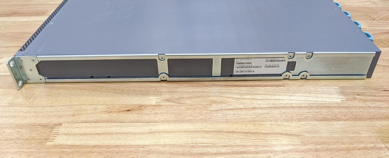
Figura 4: Lado view of the switch, showing mounting brackets and chassis design.

Figura 5: Lado opuesto view of the switch, providing another perspective of its physical dimensions.
3.2 Interfaces de gestión
The switch can be managed via its console port (CON), out-of-band management Ethernet port (C0), or in-band management through a configured network interface. The USB port can be used for software upgrades or configuration backups.

Figure 6: Close-up of the product label, showing SKU: QFX5100-48S-AFI, Serial Number (SN): TA3716510011, Part Number (PN): 650-064381 REV: 09, Manufacturing Date: 20161226, and MAC Address: 08:B2:58:C4:E0:00.

Figure 7: Close-up of the regulatory compliance label, indicating compliance with FCC Part 15, CE, UL, and other certifications. It also states "ASSEMBLED IN CHINA".
4. Mantenimiento
Regular maintenance ensures optimal performance and longevity of your QFX5100-48S-AFI switch.
- Limpieza: Keep the switch and its surroundings clean and free of dust. Use a soft, dry cloth for external cleaning. Do not use liquid cleaners.
- Flujo de aire: Ensure that the air intake and exhaust vents are unobstructed to maintain proper cooling. The fan modules are designed for specific airflow directions (e.g., "AIR OUT").
- Actualizaciones de firmware: Verifique periódicamente el soporte de Juniper Networks website for the latest firmware updates to ensure security and performance enhancements.
- Reemplazo de componentes: Power supply units and fan modules are hot-swappable. Refer to the official documentation for safe replacement procedures.
5. Solución de problemas
Esta sección cubre problemas comunes y sus posibles soluciones.
| Problema | Posible causa | Solución |
|---|---|---|
| El interruptor no se enciende. | Power cords not connected or power supply failure. | Ensure all power cords are securely connected. Check power outlets. Verify power supply unit status LEDs. |
| Port LED is off. | No link, faulty cable, or incorrect transceiver. | Check cable connection at both ends. Replace cable. Verify transceiver compatibility and proper insertion. Check remote device status. |
| System Alarm LED (ALM) is lit. | Hardware fault, temperature issue, or power issue. | Check system logs for specific error messages. Ensure proper ventilation. Verify power supply status. Contact Juniper Networks support if the issue persists. |
6. Especificaciones
| Característica | Detalle |
|---|---|
| Número de modelo | QFX5100-48S-AFI |
| Marca | Redes Juniper |
| Tipo de interruptor | Administrado |
| Número de puertos | 48 (SFP+) |
| Ranuras de expansión | 54 |
| Tipo de interfaz | PoE, SFP |
| Material de la caja | Metal |
| Color | Gris |
| Peso del artículo | 21.8 libras |
| Dimensiones del paquete | 36 x 24 x 12 pulgadas |
| Fabricante | Juniper Networks, Inc |
| Fecha de primera disponibilidad | 24 de diciembre de 2013 |
| Código Postal | 832938068032 |
7. Garantía y soporte
For detailed warranty information and technical support, please refer to the official Juniper Networks website or contact their customer service. Keep your product's serial number (found on the product label, e.g., TA3716510011) readily available when seeking support.
Puede encontrar más información y recursos de apoyo en el sitio oficial Redes Juniper websitio.
Ask a question about this manual
Ask about setup, troubleshooting, compatibility, parts, safety, or missing instructions. Manuals+ will review the question and use this page’s manual context to help answer it.