![]()
Operating instructions
EXD-SH1/2 Controller with ModBus communication
capability for electrical control valves
General information:
EXD-SH1/2 are stand-alone superheat and or temperature controllers. EXD-SH1 is intended for the operation of one bipolar electrical control valve whereas EXD-SH2 is designed for the operation of two independent bipolar electrical control valves. A table of the available application possibilities is listed below:
| Controller | Circuit 1: Main function | Circuit 2: Main function |
| EXD-SH1 | Superheat or temperature control | |
| EXD-SH2 | Superheat or temperature control | Superheat Control |
Notes:
It is possible to use only circuit 1 from EXD-SH2. In this case, circuit 2 must be disabled (C2 parameter) and the sensors and the valve for the second circuit are not needed.
Modbus communication is described in a Technical Bulletin and it is not covered by this document.
Technical data:
| Power supply | 24VAC/DC +10%/-10% 50/60HZ, |
| Power consumption | IDX-SH1: 25VA EX-SH2: 50VA |
| Plug-in connector | Removable screw terminals wire size 0.14…1.5 mm2 |
| Protection class | WOO |
| Temperature sensors | ECN-N… / TP1… (temperature range down to 45°C) ECN-Z… (temperature range down to -80°C ultra-low temperature) |
| Allowable operating/surrounding temperature | 0…+55°C |
| Maximum cable distance between EXD-SH and EXD-PM | 50 cm AWG 18 wire size (> 1mm2) |
| Pressure sensors | PT5N, PT5N-FLR or ratiometric probes |
| Output alarm relay current rating | Resistive Load 24 V AC/DC, 1 A Inductive Load 24 V AC/DC, 0.5 A |
| Contact is closed: | During alarm condition |
| Contact is open: | During normal operation and supply power OFF |
| Stepper motor output | Valves: EX4-8 (EX4-7-FLR) CV4-7 |
| Mounting | For standard DIN rail |
| Marking |
![]() Warning:
Warning:
EXD-SH1/2 (EXD-PM, ECP-024) has a potential ignition source and does not comply with ATEX requirements. Installation only in a non-explosive environment. For flammable refrigerants only use valves and accessories approved for it!
Dimensions (mm):
 Safety instructions:
- Read operating instructions thoroughly. Failure to comply can result in device failure, system damage or personal injury.
- It is intended for use by persons having the appropriate knowledge and skill.
- Before installation or service disconnect all voltages from the system and device.
- Do not operate the system before all cable connections are completed.
- Do not apply voltage to the controller before completion of wiring.
- Entire electrical connections have to comply with local regulations.
- Inputs are not isolated, potential-free contacts needed to be used.
- Disposal: Electrical and electronic waste must NOT be disposed of with other commercial waste. Instead, it is the user responsibility to pass it to a designated collection point for the safe recycling of Waste Electrical and Electronic Equipment (WEEE directive 2012/19/EU). For further information, contact your local environmental recycling center.
Temperature setting in the normal sense
(Controller function as temperature controller) Temperature setting in the reverse sense
(Controller function as temperature controller)
Electrical connection and wiring:
- Refer to the electrical wiring diagram for electrical connections.
- Note: Keep controller and sensor wiring well separated from supply power cables. Minimum recommended distance 30 mm.
- When connecting the wires of the EXV-M… (an electrical plug of valves) consider the color coding as follows:
EXV-M…: WH: White; BK: Black; BN: Brown; BL: Blue - The digital input DI1 (EXD-SH1/SH2) and DI2 (EXD-SH2) are the interfaces between EXD-SH1/2 and upper-level system controller if the Modbus communication has not been used. The external digital inputs must be free of potential (dry contact) and shall be operated in the function system’s compressor/demand.

![]() Warning:
Warning:
- Use a class II category transformer for a 24VAC power supply. Do not ground the 24VAC lines. We recommend using individual transformers for the EXDSH1/2 controller and for third-party controllers to avoid possible interference or grounding problems in the power supply.
- If EXD-PM is connected, it is mandatory to have an individual transformer for EXD-SH… and EXD-PM.
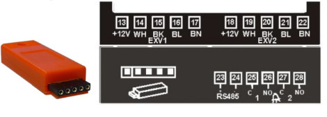
| 1 | Circuit I (EXD-SH1/SH2) | 14-17 | Electrical control valve circuit 1 (ECV I) EXV-M… Electrical plug: wire colors WH-white BK-black BL-blue BN-brown |
| (2) | Circuit 2 (EXD-SH2) | ||
| (3) | Download/upload key | 19-22 | Electrical control valve circuit 2 (ECV2) EXV-M… Electrical plug: wire colors WH-white BK-black BL-blue BN-brown |
| I and 7 | Supply voltage 24 VAC/DC | ||
| 2 and 8 | Temperature sensor circuit I | 23 and 24 | RS485 (+/-terminal) |
| 3 and 8 | Temperature sensor circuit 2 | 25 and 26 | Alarm relay circuit I (C, NO) — Suitable for re 24 VAC/DC |
| 4 and 5 | PT5N… circuit I & circuit 2 (white wire: 4 — 20 mA signal) | 27 and 28 | Alarm relay circuit 2 (C, NO) — Suitable for 24 VAC/DC |
| 9 | + I2VDC Voltage input for PT5N… (brown wire) | 29 and 30 | contact,i Digital input c rcuit I (DI I) —Dry potential-free |
| Alternative ratiometric third Party Pressure Transmitter: Warning: Read the note in the last page for limitation of error condition | 31 and 30 | Digital input circuit 2 (D12) — Dry contact, potential-free | |
| 4 and 5 | Pressure transmitter circuit 1 & circuit 2 (0.5 – 4.5 V signal) | 35 and36 | Battery/Supercapacitor connection terminal |
| 11 | + 5 VDC voltage input | 4 | Fuse: EXD-SH I (IA), EXD-SH2 (2A) |
| 10 | GND Ground | 6, 1213 18,32-34 | Not used (Terminals on EXD-SH12) |
*) Parameter 2uP with No. 9 = only pressure sensor circuit 1 is used
Preparation for Startup:
- Vacuum the entire refrigeration circuit.
- Note: EX/CV valves are delivered partially open position. Do not charge the system with refrigerant before the closure of the valve.
- Apply supply voltage 24V to EXD-SH1/2 while the digital input (DI1/DI2) is open. The valve will be driven to a close position.
- After the closure of the valve, start to charge the system with refrigerant.
Setup of parameters:
(need to be checked/modified before system start-up)
- Make sure that digital input (DI1/DI2) is open. Turn on the 24V power supply to EXD-SH1/2.
- Parameters Password (H5), type of function (1Fct), refrigerant type (1u0/2u0), pressure sensor type (1uP/2uP) and valve scaling (1uF/2uF) need to be set according to system requirement and only when digital input DI1/DI2 is open. This feature is for added safety to prevent accidental damage of compressors and other system components.
- Once the main parameters have been selected and saved, the EXD-SH1/2 is ready for startup. All other parameters can be modified at any time during operation or in system standby if it is necessary.

Display description:
| Selected main function | |||
| Su erheat control | Temperature control | ||
| Compressor ON | Compressor OFF | ||
| Upper display shows | Superheat (K/F) | Superheat (IUF) | Controlled temperature (°C/F) |
| Lower display shows | Valve opening (%) | Suction pressure (bar/ si ) | Valve opening (%) |
Instant value display mode:
- The controller displays the values of one circuit at a time, to change from one circuit to the other, press
 the button (Function only for EXD-SH2).
 - By pressing the
 key, the instant value display mode can be activated/deactivated, which allows the user to check the measured/calculated values in real-time in a sequence shown as below table:
| Value on upper display | Code on the lower display |
| Superheat (K/F) | SH |
| Valve opening (%) | OPEn |
| Suction temperature (°C/°F) | tASP |
| Suction pressure (bar/psig) | PEuA |
| Saturation temperature (°C/°F | tEuA |
| Software version: (0A) | SH1 or SH2 |
| Repeating display of values | |
Parameter configuration mode:
The configuration of parameters is protected by a numerical password. The default password is “12”. To enter the parameter configuration:
- Press both the
 and
and  buttons for more than 5 seconds.
 - A flashing “0” is displayed in the upper and “PAS” at the lower.
- Press
 until “12” is displayed; (password).
 - Press to confirm password.
- Press or to show the code of the parameter (see table of parameter codes) that has to be accessed/changed.
- Press to choose and adjust the parameter value.
- Press or to increase or decrease the value.
- Press to temporarily confirm the new value. The selected value blinks a few times and the display shows the next available parameter code.
- Repeat the procedure for other parameters if needed.
To exit and save the new settings:
- When all parameters were changed press to save all the new values and exit the parameters modification procedure.
To exit and not save the new settings:
- Press and to cancel the parameter modification and delete any changes made.
- Another way to exit without saving the changes made at the parameters is to not press any button for at least 120 seconds (TIME OUT).
- Note: While in parameter modification mode, the controller will display the parameter code on the lower display and the parameter value on the upper display.
Special manual functions: (Rest, clear)
- Press both the and buttons for more than 5 seconds.
- A flashing “0” is displayed.
- Press until “12” is displayed; (if default password has been changed, it must select the new password)
- Press to confirm password
- Select the special function as explained at the parameter configuration mode
The special functions are:
| Displayed Value | Code |
| Factory Reset | -Fdt |
| Clear Alarms (only manual reset) | ALrr |
- The default value for each variable is 0, when it set to 1 it will trigger the corresponding function.
- The factory reset of the controller (-Fdt) is possible when digital input DI1/DI2 is open.
Manual Valve operation (service /maintenance):
- Press for more than 5 seconds Select, modify and save the variables as explained at the parameter configuration mode
| Code | Parameter description and choices | Min 4 | Max | Factory setting, | Field setting |
| 1Ho | Manual mode operation; circuit 1 0 = disabled 1 = Enabled | 0 | 1 | 0 | |
| 1HP | Valve opening (%) | 0 | 100 | 0 | |
| 2Ho | Manual mode operation; circuit 2 0 = disabled 1 = Enabled | 0 | 1 | 0 | |
| 2HP | Valve opening (%) | 0 | 100 | 0 |
Note: During manual operation, functional alarms such as low superheat are disabled. It is recommended to monitor the system operation when the controller is operated manually. Manual operation is intended for service or temporary operation of the valve at a specific condition. After achieving the required operation, set the parameter 1Ho and 2Ho at 0 so the controller automatically operates the valve(s) according to its setpoint(s).
List of parameters in scrolling sequence by pressing the ![]() button:
button:


![]() Warning -Flammable refrigerants:
Warning -Flammable refrigerants:
EXD-SH1/2 (EXD-PM, ECP-024) has a potential ignition source and does not comply with ATEX requirements. Installation only in a non-explosive environment. For flammable refrigerants only use valves and accessories approved for it!
MOP default value table (°C):
| Refr. | Min. | Max. | (C°) | Refr. | Min. | Max. | (C°) | Refr. | Min. | Max. | (C°) |
| R22 | -70 | +50 | +13 | R23 | -70 | -18 | -40 | R452B | -45 | +66 | +25 |
| R134a | -57 | +66 | +15 | R32 | -52 | +30 | +15 | R454B | -40 | +45 | +18 |
| R507 | -75 | +42 | +7 | R1234ze | -57 | +66 | +24 | R454A | -57 | +66 | +10 |
| R404A | -76 | +42 | +7 | R448A | -57 | +66 | +12 | R452A | -45 | +66 | +15 |
| R407C | -66 | +48 | +15 | R449A | -57 | +66 | +12 | R444B | -45 | +66 | +15 |
| R410A | -52 | +30 | +15 | R450A | -57 | +66 | +19 | R455A | -57 | +66 | +14 |
| R124 | -45 | +91 | +50 | R513A | -57 | +66 | +13 | R1233zde | -45 | +90 | +15 |
| R744 | -40 | -4 | -5 | R290 | -66 | +48 | +15 | R1234yf | -52 | +66 | +15 |
| R407A | -66 | +48 | +10 | R1270 | -66 | +48 | +15 | ||||
| R407F | -66 | +48 | +10 | R454C | -66 | +48 | +17 |
Control (valve) start- up behavior factory settings
(1uu + 1u9) / (2uu +2u9)

| EX4/5/6 | ≤ 5.3 Seconds |
| EX7 | ≤ 5.6 Seconds |
| EX8 | ≤ 5.9 Seconds |
| CV4 | ≤ 5.3 Seconds |
| CV5/6 | ≤ 5.3 Seconds |
| CV7 | ≤ 6.6 Seconds |
Upload/download Key: Function
For serial production of systems/units, upload/download key allows the transmission of configured parameters among range of identical systems.
Uploading procedure (storing configured parameters in key):
- Insert the key while the first (reference) controller is ON and press the button; the “uPL” message appears followed by the “End” message for 5 seconds.
- Note: If the “Err” message is displayed for failed programming, repeat the above procedure.
Downloading procedure (configured parameters from key to other controllers):
- Turn off power to the new controller.
- Insert a loaded Key (with stored data from the reference controller) into the new controller and turn on the power supply.
- The stored parameters of the key will be downloaded automatically into the new controller memory; The “doL” message appears followed by an “End” message for 5 seconds.
- The new controller with the new loaded parameters setting will start to operate after the “End” message disappears.
- Remove the key.
- Note: If the “Err” message is displayed for failed programming, repeat the above procedure.
Error/Alarm handling:
| Alarm code | Description | Related parameter | Alarm relay | Valve | What to do? | Requires clear alarm after resolving alarm |
| 1E0/2E0 | Pressure sensor circuit 1/2 error | – | Triggered | Fully close | Check wiring connection and measure the signal. | No |
| 1E1/2E1 | Temperature sensor circuit 1/2 error | – | Triggered | Fully close | Check wiring connection and measure the resistance of the sensor. | No |
| 1 | Valve Circuit 1/2 electrical connection error | – | Triggered | Check wiring connection and measure the resistance of the winding. | No | |
| AFE 1/2 | Freeze protection circuit 1/2 | I P4/2P4: I | Triggered | Fully close | Check the system for causes of low pressure such as insufficient load on the evaporator. | No, if it is ON |
| AFE 1/2 | 1P4/2P4:2 | Triggered | Fully close | Yes if it is blinking | ||
| LSH 1/2 | Low superheat (<0,5K) | 1uL/2uL: I | Triggered | Fully close | Check wiring connection and operation of valve. | No if it is ON |
| LSH 1/2 | luL/2uL:2 | Triggered | Fully close | Yes if it is blinking | ||
| t4L1 | Min. temperature alarm | 1 tAL | Triggered | Fully close | Check wiring connection, operation of valve, size of valve and load. | No |
| t4H1 | Max. temperature alarm | I tAH | Triggered | Fully close | No | |
| HSH 1/2 | High superheat circuit 1/2 | luH/2uH: I | Triggered | Operating | Check the system. | No |
| LOP 1/2 | Low-pressure circuit 1/2 | 1P9/2P9 1 | Triggered | Operating | Check the system for cause of low pressure such as refrigerant loss. | No if it is ON |
| LOP 1/2 | 1P9/2P9 2 | Triggered | Operating | Yes if it is blinking | ||
| EA | Failed uploading/downloading | – | Repeat again the procedure for uploading/downloading. | No | ||
| ACEr | Modbus Timed Out | – | – | Check Modbus communication. Note: Modbus alarm (Acer) detection is active only when the pressure sensor type is configured to be Modbus type and the corresponding circuit is on demand. | No | |
| PFA | Power failure alarm | – | Triggered | Fully close | When the controller is connected to the battery supply and the power supply is interrupted, this alarm code will be displayed while the valve is closing. | No |
ACF1 or ACF2: Alarm code (circuit1/2) for “not permitted configuration/ selection” Alarm will be displayed for the following cases:
- If two circuits of the EXD-SH2 are connected to two different types of pressure transducers i.e. 4-20 mA and 0-5 V. It is mandatory that two circuits always are connected to the same type of pressure transmitter technology.
- The temperature control function is possible only with EX4-8 series valves. If other valves are used, then the ACF alarm will be displayed.
- Ratiometric pressure transmitters cannot be selected in conjunction with R744.
Notes:
- When several alarms are present, the alarms will be shown one after the other on the lower display.
- Pressure sensor error for third-party ratiometric pressure transmitters is based on the detection of interruption of two wires (5 V and signal 0.5 – 4.5 V). If only third wire (ground) is open/ interrupted, no error can be detected and the controller will receive a false signal between 50% and 100% higher. This false signal leads to improper operation of the EXD-SH1/2 controller and can lead to system/compressor damage. EMERSON is not responsible in such cases.
Service / Troubleshooting:
| Symptom | Cause | Action |
| Operating superheat is several degrees higher or lower than set-point | The incorrect signal from pressure or temperature sensors | I- Check the sensors (see list of parameters) 2- Make sure the sensor cables are not installed along with other high voltage cables |
| Operating superheat is too low i.e. compressor wet running | I – Incorrect wiring of ECVs 2- Defective sensors | I- Check the wiring 2- Check the sensor |
| Valve is not fully closed | I – The digital input is ON 2- Wrong setting of parameter ut. | I – Valve is shut off only when the digital input is turned off. 2- Check the setting of parameter ut. |
| Instable superheat (hunting) | The evaporator is designed to operate at higher superheat | Increase the superheat set-point. |
| Valve opens when EXD commands to close and vice versa | Wrong wiring between EXD-SH… and valve | Correct the wiring. |
| EX8 is not able to open at high differential pressure | Wrong setting of parameter ut | Check the parameter ut. (Larger valve requires higher torque and higher current) |
| Superheat set-point is shifting after several months of uninterrupted operation or permanent jumper of 24 V digital input | Stepper motor driven valves require synchronization | Do not jumper digital input permanently. Interrupt digital input once every week for 10 seconds if the compressor never stops. |
Emerson Climate Technologies GmbH
Am Borsigturm 31 I 13507 Berlin I Germany
www.climate.emerson.com/en-gb
Documents / Resources
 | EMERSON EXD-SH1/2 Controller [pdf] Instruction Manual EMERSON, EXD-SH1, 2 Controller, with, ModBus, communication |


