![]()
EG4® GRIDBOSS ELECTRONICS
USER MANUAL


https://eg4electronics.com/wp-content/uploads/2024/07/EG4-Grid-BOSS-User-Manual.pdf
©2024 EG4®
ELECTRONICS, LLC. ALL RIGHTS RESERVED.
VERSION 1.1.5 | INFORMATION SUBJECT TO CHANGE WITHOUT NOTICE.
MODEL #: MI-200-2P-HYB-AW-01
TECHNICAL SPECIFICATIONS
| GRID | |
| NOMINAL AC VOLTAGE | 120/240VAC (L1/L2/N required) |
| FREQUENCY | 60 Hz |
| MAXIMUM CURRENT | 200A |
| SERVICE ENTRANCE RATED | 22kAIC with 200A Eaton CSR25K (CSR2200N) breaker |
| GENERATOR | |
| NOMINAL VOLTAGE | 120/240VAC (L1/L2/N required) |
| FREQUENCY | 60 Hz |
| MAXIMUM CURRENT | 125A |
| NON-BACKUP | |
| NOMINAL VOLTAGE | 120/240VAC (L1/L2/N required) |
| FREQUENCY | 60 Hz |
| MAXIMUM CURRENT | 200A |
| BACKUP | |
| NOMINAL VOLTAGE | 120/240VAC (L1/L2/N required) |
| FREQUENCY | 60 Hz |
| MAXIMUM CURRENT | 200A |
| HYBRID | |
| NUMBER OF PORTS | 3 |
| NOMINAL VOLTAGE | 120/240VAC (L1/L2/N required) |
| FREQUENCY | 60 Hz |
| MAXIMUM CURRENT PER PORT | 90A* |
| SUPPORTED INVERTERS | EG4® 12kPV, 18kPV, & FlexBOSS21** |
| SMART PORTS | |
| NUMBER OF PORTS | 4 |
| NOMINAL VOLTAGE | 120/240VAC (L1/L2/N required) |
| FREQUENCY | 60 Hz |
| MAXIMUM CURRENT PER PORT | 1: 125A | 2: 80A | 3: 60A | 4: 60A |
| GENERAL DATA | |
| COMMUNICATION INTERFACE | RS485/Wi-Fi/CAN |
| IDLE CONSUMPTION | ~55W |
| TRANSFER TIME | ~25 ms |
| INTERNAL BUS RATING | 350A |
| INTERNAL FUSE RATING | 315A |
| OPERATING ALTITUDE | <6561 ft (<2000 m) |
| RELATIVE HUMIDITY | 0 – 100% |
| OUTDOOR RATING | NEMA 3R |
| OPERATING AMBIENT TEMPERATURE RANGE | -40°F – 140°F (-40°C – 60°C) |
| PRODUCT DIMENSIONS (H×W×D) | 31.5×19.7×7 in (800×500×178 mm) |
| UNIT WEIGHT | 55 lbs. (25 kg) |
| STANDARD WARRANTY | 10-year standard warranty*** |
| *Install a properly sized breaker based on the connected inverter: 50A – 12kPV; 70A – 18kPV; 90A – FlexBOSS21. **Third party inverters are not supported and cannot be connected to the hybrid ports. ***For information regarding warranty registration on EG4® Electronics products, please navigate to https://eg4electronics.com/warranty/ and select the corresponding product to begin the registration process. | |
STANDARDS AND CERTIFICATIONS
UL1741, UL67, UL869A*
FCC PART 15, CLASS B (PENDING)
*When used with a 200A Eaton CSR25K (CSR2200N) main breaker.
ABBREVIATIONS
- AWG – American Wire Gauge
- A – Amps
- Ah – Amp hour(s)
- AC – Alternating Current
- AFCI – Arc-Fault Circuit Interrupter
- AHJ – Authority Having Jurisdiction
- kAIC – kilo-Amp Interrupting Capability
- ANSI – American National Standards Institute
- BAT – Battery
- BMS – Battery Management System
- COM – Communication
- CT – Current Transformer
- DC – Direct Current
- DIP – Dual In-line Package
- DOD – Depth of Discharge
- EG – Equipment Ground
- EGS – Equipment Grounding System
- EMC – Electromagnetic Compatibility
- EPS – Emergency Power System
- ESS – Energy Storage System
- E-Stop – Emergency Stop
- FCC – Federal Communication Commission
- GE – Grounding Electrode
- GEC – Grounding Electrode Conductor
- GFCI – Ground Fault Circuit Interrupter
- GFDI – Ground Fault Detector/Interrupter
- Imp – Maximum Power Point Current
- IEEE – Institute of Electrical and Electronic Engineers
- IP – Ingress Protection
- Isc – Short-Circuit Current
- In-lbs. – Inch Pounds
- kW – Kilowatt
- kWh – Kilowatt-hour
- LCD – Liquid Crystal Display
- LFP – Lithium Iron Phosphate
- L1 – Line 1
- L2 – Line 2
- mm – Millimeters
- MPPT – Maximum Power Point Tracking
- mV – Millivolt
- N – Neutral
- NEC – National Electric Code
- NEMA – National Electrical Manufacturers Association
- NFPA – National Fire Prevention Association
- Nm – Newton Meters
- NOCT – Normal Operating Cell Temperature
- PC – Personal Computer
- PCB – Printed Circuit Board
- PE – Protective Earth
- PPE – Personal Protective Equipment
- PV – Photovoltaic
- RSD – Rapid Shut Down
- SCC – Standards Council of Canada
- SOC – State of Charge
- STC – Standard Testing Conditions
- UL – Underwriters Laboratories
- UPS – Uninterrupted Power Supply
- V – Volts
- VOC – Open-Circuit Voltage
- VMP – Voltage Maximum Power
SAFETY
3.1 SAFETY INSTRUCTIONS
International safety regulations have been strictly observed in the design and testing of the GridBOSS. Before beginning any work, carefully read all safety instructions, and always observe them when working on or with the inverter. The installation must follow all applicable national or local standards and regulations.
Incorrect installation may cause:
- Injury or death to the installer, operator or third party
- Damage to the inverter or other attached equipment
3.2 IMPORTANT SAFETY NOTIFICATIONS![]() DANGER: Hazardous Voltage Circuits!
DANGER: Hazardous Voltage Circuits!
There are various safety concerns that must be carefully observed before, during, and after the installation, as well as during future operation and maintenance. The following are important safety notifications for the installer and any end users of this product under normal operating conditions.
- Beware of high grid voltage. Ensure the AC switch and/or AC breaker are in the “off” or “open” position before installing or working on the inverter. Use a voltmeter to confirm there is no voltage present to avoid electric shock.
- Do not open the internal GridBOSS cover while it is operating to avoid electric shock and damage from live voltage and current within the system.
- Do not make any connections or remove any connections while GridBOSS is operating.
- An installer should make sure to be well protected by reasonable and professional insulative equipment [e.g., personal protective equipment (PPE)].
- Before installing, operating, or maintaining the system, it is important to inspect all existing wiring to ensure that it meets the appropriate specifications and conditions for use.
- Ensure the grid connections to the inverter are secure and proper to prevent damage or injuries caused by improper installation.
- Some components of the system can be very heavy. Be sure to utilize team-lift among other safe lifting techniques throughout the installation.
![]() WARNING: TO REDUCE THE RISK OF INJURY, READ ALL INSTRUCTIONS!
WARNING: TO REDUCE THE RISK OF INJURY, READ ALL INSTRUCTIONS!
All work on this product (system design, installation, operation, setting, configuration, and maintenance) must be carried out by qualified personnel. To reduce the risk of electric shock, do not perform any service other than those specified in the operating instructions unless qualified to do so.
- Read all the instructions before installation. For electrical work, follow all local and national wiring standards, regulations, and these installation instructions.
- Make sure all equipment is properly grounded. All wiring should be in accordance with the National Electrical Code (NEC), ANSI/NFPA 70.
- The system can inter-connect with the utility grid only if the utility provider permits.
Consult with the local AHJ (Authority Having Jurisdiction) before installing this product for any additional regulations and requirements for the immediate area. - All warning labels and nameplates on the inverter should be clearly visible and must not be removed or covered.
- The installer should consider the safety of future users when choosing the correct position and location for GridBOSS as specified in this manual.
- Keep children from touching or misusing the inverter and relevant systems.
- Beware! Do not connect any DC connections to GridBOSS.
![]() WARNING!
WARNING!
Cancer and Reproductive Harm – See www.P65Warnings.ca.gov for more details.
DISCLAIMER
EG4® reserves the right to make changes to the material herein at any time without notice.
Please refer to www.eg4electronics.com for the most updated version of our manuals/spec sheets.
PRODUCT OVERVIEW
The EG4® GridBOSS is a service entrance rated intelligent power distribution device that utilizes software, relays, and programmable smart ports to direct power to where and when it’s needed. There are four possible sources of AC input to support various system design needs: the grid, up to three hybrid inverters, a generator, and AC coupling ports. The system can output power to the backup loads port, smart ports, and the non-backup loads port. Common uses for smart ports include power shedding for various loads such as electric vehicles, water heaters, and HVAC units. Smart ports are also used for attaching AC coupled PV, which provides another source of power. The unit supports an AC pass-through current of up to 200 amps, providing end users with intelligent distribution solutions.
Common application scenarios are shown in the image below, with the configuration steps shown in section 6.

![]() IMPORTANT:
IMPORTANT:
The breakers displayed in the image above are the maximum supported sizes for each port. The maximum allowed total output amperage is set at 200 amps.
If the current draw exceeds 200A, GridBOSS will begin to limit load output.

| ITEM | DESCRIPTION |
| 1 | Wi-Fi dongle |
| 2 | RSD/ESS switch |
| 3 | Chassis handles |
| 4 | Door latches |
| 5 | Door lock mechanism for padlock |
| 6 | Port LEDs |
| 7 | Smart port breakers |
| 8 | Hybrid port breakers |
| 9 | Manual bypass bracket |
| 10 | Backup port breaker |
| 11 | Manual bypass breaker |
| 12 | Generator breaker |
| 13 | Grid breaker (optional) |
4.1 DIMENSIONS

| U.S. NOMINAL TRADE SIZE | ACTUAL SIZE |
| 1/2 in. | 0.90 in. (22.9 mm) |
| 3/4 in. | 1.14 in. (28.9 mm) |
| 1 1/2 in. | 1.98 in. (50.4 mm) |
| 2 in. | 2.48 in. (63 mm) |
4.2 PACKING LIST
The items listed below will arrive with each product shipment:

*Included breakers: 30A (x1), 40A (x1), 60A (x2), 80A (x1), 90A (x3)
INSTALLATION
This section provides detailed steps for installing and configuring the GridBOSS. It is recommended to complete each section in order as listed below.
Installation Steps:
5.1 Mounting area and spacing requirements
5.2 Recommended tools
5.3 Mount the unit
5.4 Install breakers
5.5 Install cables
5.6 Configure hybrid inverters
5.7 Configure GridBOSS
5.8 Verify Configuration
5.1 MOUNTING AREA & SPACING REQUIREMENTS
Follow the requirements listed below for system installation:
- The mounting wall must be strong enough to bear the weight of all equipment (GridBOSS, inverters, wall mounted batteries, etc.).
- Maintain the minimum clearances on all sides (see next page).
- Ensure the mounting surface is made of non-combustible material.
- Ensure the final installation location has adequate room for making electrical connections and servicing the unit.
- Never position the GridBOSS in direct sunlight.
- The installation location must have a maximum relative humidity of 100%.
- The location must have a minimum ambient temperature of -40°F (-40°C) and a maximum ambient temperature of 113°F (45°C).
- Do not install the equipment in an environment near combustible materials.
- The maximum supported distance between GridBOSS and attached hybrid inverters is 300 feet.
This distance is set in order to support communication between the GridBOSS and the inverter using a CAT5 or higher specification straight-through network cable in the 568B format. - When mounting the unit, ensure the installation location complies with local codes and UL514B requirements.
- Position the unit on a vertical surface. Do not install the unit upside down!


Be sure to maintain the spacing requirements shown in the image to allow access to fully open the door and to view the dongle LEDs.
Ensure there is adequate space in front of the unit to allow for working space and clearance for the front cover to swing open.

GridBOSS is designed to be wall mounted using the included wall mount bracket.
It should be installed vertically on a solid, non-combustible surface such as brick or concrete.
The slots on the mounting bracket can accommodate various stud spacings from 12 in. (305 mm) to 16 in. (406 mm).
5.2 RECOMMENDED TOOLS

5.3 MOUNT THE UNIT
- Select a suitable location to install the GridBOSS as described in section 5.1.
- Use the wall mounting bracket as a template to mark where the screws will be installed. When installing the wall bracket to studs, verify the marks for the screws are centered over a stud.

- When installing the bracket to concrete or brick, drill 25/64inch (10 mm) diameter holes on the marks, making sure the holes are deeper than 3-3/16 in. (80 mm) when using the included expansion bolts.
When installing the bracket to a stud, drill a pilot hole recommended for the screw diameter used. (screws not included)
For concrete or brick wall installation, insert the expansion bolts into the drilled holes. Install the bracket to the wall ensuring the arrow is pointing up. Use the corresponding nuts and washers (packaged together with the expansion bolts) to affix the bracket to the wall.
For st ud wall installation, use the proper screws and affix the bracket to the wall.
Using the team-lift technique, place the GridBOSS onto the wall bracket securing it to the wall.

Temporarily mount the L-bracket to the side of the GridBOSS (located at the bottom, one on each side).
Place a mark on the wall based on the hole location inside the L-bracket. Repeat this step for both sides.
Remove the L-bracket and drill a hole at the marking. Use the drill bit size based on the anchor type or screw size as directed in step 3. Repeat this step for both sides.

Attach the L-brackets (one on each side) to the GridBOSS and to the wall using the correct hardware. Once the bracket is secure, the wall installation is complete.

5.4 INSTALL BREAKERS
This section provides the steps to install the 2-pole breakers that are included with the GridBOSS, as well as the optional main breaker.
To begin the installation, open the front door by releasing the clasps on the right side of the unit.
Next, remove the four screws as identified in the image below and then carefully remove the inner black cover by lifting it out of the chassis. Once the cover is removed, use the information in this section for guidance on installing each breaker.
![]() DANGER:
DANGER:
If a breaker is installed after the system is in operation, verify all breakers are in the off position and there is no voltage at each breaker and lug connection point.

Breaker Placement and Installation:
Use the table below when installing the breakers supplied from the packing list.
| SIZE | QUANTITY SHIPPED | SUPPORTED PORT LOCATIONS |
| 30A | 1 | Smart Ports 1 – 4 & Generator |
| 40A | 1 | Smart Ports 1 – 4 & Generator |
| 60A | 2 | Smart Ports 1 – 4 & Generator |
| 80A | 1 | Smart Ports 1 & 2 & Generator |
| 90A | 3 | Hybrid Ports 1-3 and Smart Port 1 |
If an additional breaker size is needed, use the chart below to identify the breaker size supported at each port location. Ensure any additional breakers are purchased from an EG4® distributor to ensure a supported breaker model is installed.
| PORT | SUPPORTED BREAKER SIZES | MODEL # | SOURCE |
| Grid | 200A | Eaton CSR25K (CSR2200N) | Anywhere |
| Non-Backup | No breaker, lug only | – | – |
| Backup | 200A (pre-installed, non-changeable) | B3T1-200 | EG4 |
| Manual Bypass | 200A (pre-installed, non-changeable) | B3T1-200 | EG4 |
| Generator | 30A, 40A, 60A, 80A, 100A, 125A | B3S1 – 30, 40, 60, 80, 100, 125 | EG4 |
| Hybrid 1 – 3 | 12kPV: 50A 18kPV: 70A FlexBOSS 21: 90A | B3S1 – 50, 70, 90 | EG4 |
| Smart Port 1 | 90A, 100A, 125A | B3S1 – 90, 100, 125 | EG4 |
| Smart Port 1 & 2 | 70A, 80A | B3S1 – 70, 80 | EG4 |
| Smart Port 1 – 4 | 30A, 40A, 50A, 60A | B3S1 – 30, 40, 50, 60 | EG4 |
Breaker Installation:
When installing a 2-pole breaker, hold the breaker at an angle and place the bottom slot of the breaker on the metal bracket inside the GridBOSS chassis. Then pivot the breaker towards the chassis until the top of the breaker snaps onto busbar blades.

Optional Main Breaker Installation:
- Remove the internal orange cover by first removing the two nuts using a 7mm socket and the four screws using a Phillips screwdriver. Then lift the cover out of the unit.

- With the inside cover removed, locate the lugs for both line 1 and line 2 (outlined with dashed line). Remove the screw holding each lug in place then remove each lug.
Remove the small Phillips head screw (circled) and set it aside. This screw will be reinstalled in a later step with the main breaker.
- Before installing the breaker, adjust the position of the insulation sheet by moving the end to the right side.

- Install the 200A Eaton CSR25K (CSR2200N) breaker by sliding it into place, aligning the bolt holes in the breaker lugs to the holes on the busbar.

- Using a 10 mm socket, install the two M6 screws in the busbar, then install the M4 screw that holds the opposite end of the breaker in place.
Tighten the M6 screws to 80 in-lbs. (9Nm) and the M4 screw to 10 in-lbs. (1.2Nm).
When installing the conductors to the main breaker terminals, use a 1/4-inch hex wrench and torque to 250 in-lbs. (28Nm). - Install the orange inner cover plate removed in step 2.

5.5 INSTALL CABLES
Use the information in this section for guidance on connecting the AC wiring. Using a multimeter, verify each wire is not carrying voltage/current before making a connection to the GridBOSS.
![]() WARNING:
WARNING:
Use ONLY COPPER WIRE for ALL GridBOSS connections! Failure to use copper wire could result in equipment damage as the unit has not been approved to accept other types of wiring. This includes the connections to all GridBOSS lugs and breakers, regardless of breaker rating.![]() IMPORTANT:
IMPORTANT:
GridBOSS is Service Entrance Rated and certified under UL869A only when installed with a 200A Eaton CSR25K (CSR2200N) breaker.
SYSTEM GROUND
The ground busbar supports connecting GridBOSS to the building’s equipment grounding system and to the building’s grounding electrode system if using GridBOSS as service entrance equipment. The ground cable should be installed first to provide a solid ground during the wiring installation process.
| LUG COUNT | MAX. SUPPORTED WIRE SIZE | MAX. TORQUE VALUE | HEX TOOL SIZE |
| 8 | 6 AWG THHN | 40 in-lbs. (4.5Nm) | 1/8 inch |
| 6 | 3 AWG THHN | 5/32 inch |

NEUTRAL WIRING AND BONDING
The neutral busbar supports interconnection of the neutral wires in the electrical system.
| LUG COUNT | MAX. SUPPORTED WIRE SIZE | MAX. TORQUE VALUE | HEX TOOL SIZE |
| 7 | 6 AWG THHN | 40 in-lbs. (4.5Nm) | 1/8 inch |
| 2 | 3/0 AWG THHN | 70 in-lbs. (7.9Nm) | 3/16 inch |
| 3 | 4/0 AWG THHN | 230 in-lbs. (25.9Nm) | 5/16 inch (8 mm) |

NEUTRAL GROUND BOND
The unit ships with a neutral-ground bonding jumper (bracket) that connects the ground busbar to the neutral busbar. This should only be attached if GridBOSS is the first service disconnect, as there can only be one neutral bond connection in the electrical system.
For example, the bonding jumper would most commonly be used if GridBOSS is installed directly after the power meter and is set up as the first service disconnect. In this configuration, the 200A Eaton CSR25K (CSR2200N) breaker must be installed in GridBOSS.

If a first service disconnect is already installed after the power meter, GridBOSS will be attached in series with the existing first service disconnect. In this case the bonding jumper should not be used.
If there are questions concerning the neutral ground bond, contact a licensed electrician for assistance.
![]() IMPORTANT:
IMPORTANT:
The system should have one and only one neutral-ground bond. (This is typically the main bonding jumper located at the first service entrance disconnect.)
GRID PORT
The grid input supplies power to the GridBOSS in a grid-assisted configuration. There are two configuration options when connecting to the grid. The first option uses lugs, which are factory installed.
The second option uses the 200A Eaton CSR25K (CSR2200N) breaker, which is optional and must be purchased separately. To install the 200A Eaton breaker, follow the steps in section 5.4.

Reference the table below for wire size and torque recommendations when connecting the grid port wiring.
| BREAKER SIZE | MAX. SUPPORTED BREAKER SIZE | MAX. SUPPORTED WIRE SIZE | MAX. TORQUE VALUE | TOOL SIZE |
| Lugs | – | 4/0 AWG – 250 kcmil | 275 in-lbs. (31Nm) | 8 mm hex |
| 200A (optional) | 200A | 4/0 AWG – 300 kcmil | 250 in-lbs. (28Nm) | 1/4-inch hex |
GENERATOR PORT
GridBOSS can utilize supplemental 240VAC generator power for backup and battery charging in the case of a grid failure. The generator port can supply power to the backup port, the hybrid ports, and configured smart ports when the grid power goes down. To support automatic generator startup, the GridBOSS has a 2-wire start/stop terminal for controlling 2-wire start capable generators
It is highly recommended to choose a generator that is at least less than 12% Total Harmonic Distortion (THD) for optimal performance of the GridBOSS. To achieve a lower THD value, it is recommended to size the generator by at least 1.5x the total output of all inverters to allow for powering loads and charging batteries.

![]() NOTE:
NOTE:
When operating a hybrid inverter with GridBOSS, all generator support will come directly through the GridBOSS generator port. The generator port on each hybrid inverter must not be used.
Reference the table below for wire size and torque recommendations when connecting the generator port wiring.
| SUPPORTED BREAKER SIZE | MAX. SUPPORTED WIRE SIZE | MAX. TORQUE VALUE |
| 80A, 100A, 125A | 2 – 1/0 AWG | see torque value printed on breaker |
| 30A, 40A, 60A | 10 – 4 AWG |
GENERATOR OPERATION
The attached generator can only be started when utility grid is lost, and the generator is wired for 2-wire stop/start using the “Dry 1” contacts on the communications board. The internal grid relay and the internal generator relay cannot be closed at the same time to ensure generator output does not send power to the grid.
GridBOSS should use start/stop relay 1 in the normally open connection. Start/stop relay 1 can be controlled by both manual control and by battery SOC/voltage logic within the EG4® Monitor Center.
The generator can also be configured with warm-up, cool-down, and exercise time.
The GridBOSS generator relay can only be closed after start/stop relay 1 is closed. When start/stop relay 1 is closed, GridBOSS must wait until the generator is able to supply stable output power. This wait time is configured using the generator warm-up time setting in the EG4® Monitor Center. Once the generator warm-up time is complete, GridBOSS will close the generator relay. Before the generator can be safely powered off, the generator must complete the cool-down time. Once the cool-down time is complete, GridBOSS will open the generator relay and then open start/stop relay 1. The Start/Stop relay 1 connection is labeled Dry 1 on the GridBOSS cover plate. The Dry 2 connections are currently unused and reserved for future use.

- COM1 and NC1 are a set of normally closed switches
- COM1 and NO1 are a set of normally open switches
- COM2 and NC2 are a set of normally closed switches
- COM2 and NO2 are a set of normally open switches
NON-BACKUP LOADS PORT
The non-backup loads port is used to pass-through power from the Grid input to loads that either do not require backup or that are wanted to be purposely omitted from the backed-up loads in order to not overload the inverter during an outage. Loads connected to this port will not have power during a grid outage. Using smart ports may serve as a better option for loads that might overload the inverter upon start-up but have the advantage of being backed up if there is sufficient power from the inverters during a grid outage.

![]() NOTE:
NOTE:
The breaker above the non-backup port is not connected to the non-backup port lugs and is not used by the non-backup port. This breaker is used when activating manual bypass mode.![]() CAUTION:
CAUTION:
The non-backup port is not controlled by a breaker or relay and will always receive current if GridBOSS is supplied with grid input.![]() WARNING:
WARNING:
The non-backup port does not have built in overcurrent protection at the port output. An external breaker MUST be installed with the proper amperage rating to protect the wire size used. The breaker cannot exceed a 200A rating.
Reference the table below for wire size and torque recommendations when connecting the non-backup port wiring.
| BREAKER SIZE | MAX. SUPPORTED BREAKER SIZE | MAX. SUPPORTED WIRE SIZE | MAX. TORQUE VALUE | TOOL SIZE |
| Lugs | Lugs only | 4/0 AWG – 250 kcmil | 275 in-lbs. (31Nm) | 8 mm hex |
BACKUP LOADS PORT
The backup loads port provides power to any panel the needs to be backed up by the EG4 energy storage system. This could be the home’s main breaker panel, a critical loads subpanel, or any combination of main panels and subpanels.

![]() CAUTION:
CAUTION:
The backup loads port CANNOT be fed to a load panel that is also fed by power from another source such as utility, generator, or AC coupled solar unless a manual transfer switch is used.![]() IMPORTANT:
IMPORTANT:
When operating an EG4 hybrid inverter with GridBOSS, the inverter’s load port will remain unused and should be in the off position. The inverter’s grid port supports both grid input and output based on the inverter’s settings. Critical loads will be cabled to and powered by the backup loads port on GridBOSS
Reference the table below for wire size and torque recommendations when connecting the backup port wiring.
| MAX. SUPPORTED BREAKER SIZE | MAX. SUPPORTED WIRE SIZE | MAX. TORQUE VALUE | TOOL SIZE |
| 200A (preinstalled) | 4/0 AWG – 250 kcmil | 275 in-lbs. (31Nm) | 8 mm hex |
HYBRID INVERTER PORTS
GridBOSS hybrid ports connect to supported EG4® hybrid inverters. When cabling the AC connection to the hybrid inverter, only connect the inverter’s grid port to the GridBOSS hybrid port. See the chart below for supported EG4 hybrid inverters.
![]() WARNING:
WARNING:
The only inverters that can be connected to the hybrid ports are the 12kPV, 18kPV and FlexBOSS21. DO NOT connect any other inverter to the hybrid ports as this could cause damage to the inverter being connected to the GridBOSS.![]() WARNING:
WARNING:
Use the proper breaker sizing and wiring requirements as described in the table below for each hybrid inverter. Do not use a breaker rated higher than what is supported, damage could occur to the equipment.![]() IMPORTANT:
IMPORTANT:
When operating a hybrid inverter connected to GridBOSS, the inverter’s load port must be unused and turned off. The inverter’s grid port supports both input and output power based on the inverter’s settings.

Reference the table below for wire size and torque recommendations when connecting the hybrid port wiring.
| HYBRID PORT | SUPPORTED INVERTER MODEL | MAX. SUPPORTED BREAKER SIZE | MAX. SUPPORTED WIRE SIZE | TORQUE VALUE |
| 1 – 3 | 12kPV | 50A | 6 AWG | see torque value printed on breaker |
| 18kPV | 70A | 4 AWG | ||
| FlexBOSS21 | 90A | 2 AWG |
SMART PORTS
Smart ports are designed to support powering smart loads or accepting AC coupled inverter inputs. The ports are controlled by an internal relay that is configured in the EG4® Monitor Center. Each port can also be manually switched on or off using the breaker. Each smart port is individually configured and has different load specs as outlined in the table below.
When using the smart ports configured for smart loads, the attached devices can be powered on or off according to grid presence, time of use (TOU), battery state of charge (SOC/Voltage), and PV state.
When using the smart port with an AC coupled inverter, additional power can be injected into the ESS system from the PV array connected to the inverter.

![]() NOTE:
NOTE:
When operating a hybrid inverter with GridBOSS, smart port functionality is moved from the hybrid inverter to GridBOSS. All devices that connect through a smart port must be cabled directly to a GridBOSS smart port. Select GridBOSS in EG4® Monitor Center when configuring a smart port.
Reference the tables below for wire size and torque recommendations depending on the type of wire and connection.
| SMART PORT # | SUPPORTED BREAKER SIZES | MAX SUPPORTED WIRE SIZE | MAX TORQUE VALUE |
| 1 | 90A, 100A, 125A | 2 – 1/0 AWG | see torque value printed on breaker |
| 1 & 2 | 70A, 80A | 4 – 3 AWG | |
| 1 – 4 | 30A, 40A, 50A, 60A | 10 – 4 AWG |
RAPID SHUTDOWN & ESS DISCONNECT
GridBOSS supports a rapid shutdown system that complies with 2017 and 2020 NEC 690.12, and ESS Disconnect that complies with NEC 706.15 requirements. The rapid shutdown switch on the right side of GridBOSS, when used, will initiate total system shutdown including the inverters, supported batteries, and PV (if properly equipped). When connecting GridBOSS to EG4® hybrid inverters, the RSD wiring only needs to connect to the master inverter. When using an external RSD/ESS initiator, it is installed inline between the inverter and GridBOSS as shown in the image below.
![]() NOTE:
NOTE:
When using supported EG4 batteries in closed-loop communications with the inverter, the RSD also initiates ESS Disconnect.
The system can utilize an external RSD/ESS initiator (switch) that can be placed near the service entrance and in full sight of first responders. If installing an external RSD/ESS initiator, it must use normally closed contacts for emergency shutdown.

REPLACE CABLE BOX COVER
Before replacing the cable box cover, remove any knockouts where a breaker was installed. The knockouts are designed to be rocked back and forth until the small connection point between the knockout and the cover is broken allowing the knockout to be removed. Install the grid and generator cover plate if breakers are not installed in those areas. Before powering up the unit, reinstall the cable box cover. The image below shows all hybrid and smart port breakers installed. No main breaker or generator breaker is installed so the cover plates are attached to the cable box cover.

5.6 CONFIGURE THE HYBRID INVERTERS
As best practice, configure the hybrid inverter(s) before configuring the GridBOSS. When configuring each inverter, note the following:
- Utilize only battery power for the inverters during the initial configuration. The GridBOSS should remain powered off. The inverter grid port cannot be connected directly to the grid.
- Do not install the inverter’s CT clamps since GridBOSS has internal CT clamps.
- Verify the battery or battery bank and PV array connected to the inverter(s) are fully functional.
- If using more than one inverter, verify they are set up in a functioning parallel configuration.
- Do Not connect the inverter’s load port to GridBOSS. The inverter’s load port must remain in the off position.
- Do Not cable anything to the inverter’s generator port (if equipped). The inverter’s generator breaker should remain in the off position. All smart load functionality, AC couple functionality, and generator functionality will be connected to and configured on the GridBOSS.
- Install at least the minimum firmware required on each inverter as shown in the chart below.
Please refer to the inverter documentation linked below for detailed instructions on installation and configuration guidance:


![]() NOTE:
NOTE:
Verify each hybrid inverter has the minimum required firmware version installed to support connectivity with GridBOSS. Each inverter uses system firmware. The 12kPV and 18kPV also use LCD firmware, which supports the front panel LCD screen. For more information on updating firmware, see section 9 of this manual.
| INVERTER | MIN. SYSTEM FIRMWARE | MIN. LCD FIRMWARE |
| 12kPV | FAAB-1E1E | V18 |
| 18kPV | FAAB-1E1E | V18 |
| FlexBOSS21 | FAAB-1E1E | N/A |
5.7 CONFIGURE GRIDBOSS
Before configuring the GridBOSS, verify the following:
- The inverter(s) are fully configured and using at least the minimum firmware required to operate with the GridBOSS. This should have been completed in the previous section.
- Each hybrid inverter is powered off.
- All GridBOSS breakers are in the off position.
- If a main breaker is not installed in the GridBOSS, verify the source providing power to the GridBOSS is in the off position.
- If the non-backup port is cabled to an electrical panel, verify the breaker in that panel is in the off position. Do not switch on the electrical panel main breaker until GridBOSS is completely configured.
- Use a multimeter to verify there is no voltage/current present at each GridBOSS lug and breaker before proceeding with the steps below.
- Connect the communication cable between GridBOSS and the inverter(s) using the images below as reference. The GridBOSS DIP switches should remain in the down position (ON) as shipped from the factory. Also note, the GridBOSS DIP switch On and Off positions are flipped 180 degrees as compared to the inverters.
NOTE:
If the communications cable needs to be replaced or a longer cable is needed, use a CAT5 or higher specification straight-through network cable in the 568B format. The communications cable cannot be longer than 300 feet.

- Power on the inverter(s), starting with the master in a parallel configuration. The inverters should only be powered by a battery or battery bank.
- Enable the “Grid Boss” setting on the inverter (master inverter in a parallel configuration). The 12kPV and 18kPV can be configured using the front LCD panel. When configuring FlexBOSS21, use the EG4® Monitor Center website or the optional EG4 LCD Screen Kit (available separately).
• LCD Panel: Navigate to the Advanced page and select the “Grid Boss” setting and then select the “Set” button to save the setting. • Monitor Center: Select the “Maintenance” tab and then select “Working Mode” in the upper right area of the screen. Expand “Application Setting” and then select “Advanced Settings”. Select “Enable” next to the “Grid Boss Enable” setting.
- Switch the GridBOSS hybrid inverter breaker(s) to the on position. This should power on the GridBOSS using the inverter’s grid port as the power source. If the “Grid Boss Enable” setting was not enabled in the previous step, GridBOSS will not power on.
- Verify the GridBOSS hybrid LED is illuminated and is solid green.
- Verify all grid settings are configured appropriately based on enabling or disabling grid sell back settings. All grid sell back functionality is configured within the inverter settings. FlexBOSS will require the use of the EG4 Monitor Center or mobile app or the external EG4 LCD screen kit.
- Enable grid input to the GridBOSS by turning on the grid breaker (if equipped) or by turning on the breaker providing grid access.
5.8 VERIFY CONFIGURATION
- Visually inspect the GridBOSS’ front panel LEDs. The “Grid” and “Hybrid” LEDs should be solid green. If there is a flashing LED, see section 12 for additional troubleshooting information.
- Verify inverter settings using the LCD or Monitor Center:
Using the LCD Panel:
Verify the settings shown below using the inverter’s LCD panel. The inverter will also display a small green MID Box icon on the bottom left of the home page. • Role: Verify GridBOSS has only ONE master inverter. The master inverter should be set to “1 Phase primary” and all other inverters should be set to “Slave”. Remember to press the “Auto Detect Phase” reset button if any changes are made to the parallel settings.
• Share Battery: Select “share battery” if the inverters are sharing a single battery bank. Do not select “share battery” if each inverter is connected to a dedicated battery.
• Grid Boss: Verify “Grid Boss” is checked for all parallel inverters connected to GridBOSS hybrid ports. NOTE:
NOTE:
When a 12kPV or 18kPV inverter is connected to GridBOSS, the inverter’s LCD main page will show the total power values for the entire system, which is different from parallel systems without GridBOSS. “Grid Power” on the main page is equal to the GridBOSS grid power value. “Home Load” shows all the load power going through GridBOSS. “AC Couple” power shows all the AC couple smart port’s power.
Using Monitor Center:
Select the “Maintenance” tab and then select “Working Mode” in the upper right area of the screen.
Expand “Application Setting” and then select “Advanced Settings”. Select “Enable” next to the “Grid Boss Enable” setting. • Grid Boss Enable: Verify “Grid Boss Enable” is enabled for each inverter connected to a GridBOSS hybrid port.
• Set System Type : Verify GridBOSS has only ONE master inverter. The master inverter should be set to “1 Phase Master” and all other inverters should be set to “Subordinate”.
• Share Battery: Select “share battery” if the inverters are sharing a single battery bank. Do not select “share battery” if each inverter is connected to a dedicated battery. - Check each inverter and verify there are no errors or warnings. If there are any issues, see the inverter documentation for additional troubleshooting information.
- The system is now ready for use and can be further configured with advanced features such as auto generator start, smart loads, and AC coupling.
SYSTEM OPERATION & CONFIGURATION EXAMPLES
GridBOSS must be set up with at least one powered input in order to power up and be ready for operation. The input can be from the grid, a hybrid inverter, or from a generator. GridBOSS acts as a power distribution unit that controls the flow of power using internal relays and software. When configuring settings for the inverters or for GridBOSS, be sure to select the proper corresponding serial number in the EG4® Monitor Center or the mobile app.
6.1 HYBRID INVERTERS
When using hybrid inverters with the GridBOSS, the settings for grid interactivity are configured at the inverter. GridBOSS can only control the ports within the chassis by opening or closing each individual port relay. The inverters communicate with GridBOSS using a communication cable which shares configuration settings, current and voltages, and any data needed to direct power output.
No Grid Sell Back
In this example, grid sell back is disabled within the inverter’s settings. This supports grid assist for powering the backup loads, smart loads, and charging battery storage. Since the non-backup loads port is not controlled by a separate relay, it will receive power from the grid only.

Inverter Settings:
Application:
Power Backup: Enable
Grid Sell Back: Disable
Fast Zero Export: Enable
Off-Grid Mode: Disable
Charge:
AC Charge: Enable or Disable based on need
GridBOSS Settings:
No setting changes required
Grid Sell Back
In this example, grid sell back has been enabled within the inverter settings. When the inverter provides power to the loads, the priority is to power the backup loads first, then any extra power will go to the non-backup loads. Power will also be supplied to the smart loads, where the priority is set within the smart load settings. To include battery power with grid sell back, enable “Forced Discharge Enable”. To only use PV with grid sell back, enable “PVSellToGrid (Comp. w/ NEM3.0)”. To maximize grid sell back, consider load shedding non-critical loads using the smart ports.” The grid will assist providing power to non-backup loads, backup loads, and the smarts ports as needed.

Inverter Settings:
Application:
Power Backup: Enable
Grid Sell Back: Enable
Fast Zero Export: Disable
Off-Grid Mode: Disable
Charge:
AC Charge: Enable or Disable based on need
Discharge:
Forced Discharge Enable: Disable
PVSellToGrid (Comp. w/ NEM3.0): Enable
GridBOSS Settings:
No changes required
Off-Grid Mode
In this example, the inverter’s “Off-Grid Mode” is enabled. The backup loads and the smart loads will either be powered by the inverter(s), or the grid. Grid will not provide supplemental power to the backup loads or the smart loads, but the grid can be used to charge the battery. The non-backup loads can only be powered by the grid.

Inverter Settings:
Application:
Power Backup: Enable
Grid Sell Back: Disable
Fast Zero Export: Enable
Off-Grid Mode: Enable
GridBOSS Settings:
No setting changes required
6.2 GENERATOR
In this example, a generator has been added to the GridBOSS to power the backup loads and to supplement charging the batteries, if needed. The generator breaker and the generator relay are in the closed position allowing current to flow to the backup loads. Generator output could assist in charging the batteries as long as the proper settings are configured, and the loads are small enough leaving the extra power from the generator to charge the batteries. If a small generator is used that cannot fully power the critical loads, enable “Generator Boost” at the inverter. Verify the generator start/stop wiring is properly connected to support generator start and stop functionality. The smart ports in the example below will not receive current unless the ports are set up for operation in the EG4® Monitor Center.

GridBOSS Settings:
MIDBOX:
Charge Control: SOC
Discharge Control: SOC
GENERATOR:
Generator SOC/Vbat Enable: Enable
Batt Charge Current Limit (Adc): 250
Gen Rated Power (kW): 25.5
Charge Start SOC: 50%
Charge End SOC: 80%
Generator Warm Up Time(s): 120
Generator Remote Auto Turn off time(m): 20
Inverter Settings:
Application:
Grid Sell Back: Enable or Disable
Fast Zero Export: Disable or Disable
Off-Grid Mode: Disable or Disable
Charge:
AC Charge: Enable or Disable
Generator Charge:
Generator Boost: Enable or Disable
6.3 MANUAL BYPASS MODE
In this scenario, all the relays in GridBOSS are bypassed allowing grid current to flow directly to the backup loads port powering the critical loads panel. The bypass mode was set up to support critical loads in the unforeseen circumstance the GridBOSS needs to be bypassed. The non-backup loads port also receives power from the grid when in bypass mode.


To enable manual bypass:
- Set the “Backup” load breaker to the off position.
- Slide the manual bypass bracket all the way to the left.
- Set the “Manual Bypass” breaker to the on position.
6.4 SMART LOADS
In this scenario, a water heater and an electric car charger are connected to smart ports 2 and 3.
There are multiple ways a smart port can be configured using the EG4® Monitor Center and this section will cover a few of those ways. The first option is to manually set the port to be always on or always off. The second option is to turn the port on or off based on battery SOC and/or time periods.
Another option is using load shedding, which adds the additional setting for PV input level.
![]() NOTE:
NOTE:
Smart port functionality is not supported at the hybrid inverter when attached to a GridBOSS. All devices that are powered by a smart port must be connected directly to a GridBOSS smart port.

See the next page for example configurations.
All smart load settings are configured on the GridBOSS.
Each smart port is configured individually based on the device attached and usage.
Example Configurations:
- Always On: The following examples show how to configure a smart load to be always enabled.
This can be done in two ways either by using the “Grid Always On” setting, or by using the “Time” setting. Using “Grid Always On” enables the smart port when there is grid input. If the grid goes down the relay will open, and the smart port will no longer receive power. When using time to enable the smart port, disable “Grid Always On” and set the start and end times to be enabled for a 24-hour time period as shown below.
MIDBOX:
Charge Control: SOC
Discharge Control: SOC
MidBox Smart Port #:
Smart Port Mode: Smart Load
Smart Load Enable: Enable
Smart Load Grid Always On: Enable
OR
MIDBOX:
Charge Control: SOC
Discharge Control: SOC
MidBox Smart Port #:
Smart Port Mode: Smart Load
Smart Load Enable: Enable
Smart Load Grid Always On: Disable
Smart Load Start Time: 00:00
Smart Load End Time: 23:59 - Set the smart load to be active when the battery SOC is above 70% between the hours of 4pm – 8pm. The smart load will be disabled after 8pm or when the battery falls below 30% SOC.
MIDBOX:
Charge Control: SOC
Discharge Control: SOC
MidBox Smart Port #:
Smart Port Mode: Smart Load
Smart Load Enable: Enable
Smart Load Grid Always On: Disable
Smart Load Start & End SOC(%): 70% and 30%
Smart Load Start Time: 16:00
Smart Load End Time: 20:00 - Set the smart load to be active when PV is at least 1600w, battery SOC is above 70% and time is between the hours of 1pm – 6pm. All three of these conditions must be met for the smart port to be enabled.
MIDBOX:
Charge Control: SOC
Discharge Control: SOC
MidBox Smart Port #:
Smart Port Mode: Smart Load
Smart Load Enable: Enable
Start Load Use Shedding Mode: Enable
Smart Load Power Shedding Start PV Power(W): 1600
Smart Load Power Shedding Start & End SOC(%): 70% and 30%
Smart Load Start Time: 13:00
Smart Load End Time: 18:00
6.5 AC COUPLING
In this scenario, existing AC coupled PV is added to the smart port 1. Smart port 1 is used for this example but any smart port can be configured for AC coupling. The extra power provided by AC coupled PV can be utilized by various loads in the system. See the example configurations on the next page for more details.

See the next page for example configurations. Each smart port is configured individually based on the device attached and usage.
![]() WARNING:
WARNING:
Verify the AC coupled device is UL1741, UL1741SA, and UL1741SB certified.
Uncertified devices may cause hardware damage to the equipment.![]() NOTE:
NOTE:
Smart port functionality is not supported at the inverter generator port when attached to a GridBOSS. All AC coupled devices must be connected directly to a GridBOSS smart port.
Example Configurations:
Grid Sell Back: The inverter is configured for grid sell back and AC coupling will be used as supplemental power to the backup port, smart loads, non-backup port, and to assist with charging the batteries. Once the batteries are fully charged, AC coupled power will continue to assist with powering loads. This configuration will only work when grid input is present.
GridBOSS Settings:
MIDBOX:
Charge Control: SOC
Discharge Control: SOC
MidBox Smart Port #:
Smart Port Mode: AC Couple
AC Couple Enable: Enable
AC Couple Start & End SOC%: 30% & 100%
AC Couple Start Time: 00:00
AC Couple End Time: 23:59
Inverter Settings:
Application:
Power Backup: Enable
Grid Sell Back: Enable
Fast Zero Export: Disable
Off-Grid Mode: Disable
Charge:
AC Charge: Enable
Off Grid Mode: In this example, the AC coupling configuration is only applicable when there is no grid present. If the grid is present, the AC coupled inverter will not output power. The inverter is configured for off-grid mode and AC coupling will be used as supplemental power to the backup port, smart loads, non-backup port, and to assist with charging the batteries. Once the batteries are fully charged, AC coupled power will continue to assist with powering loads. In this configuration, the non-backup port cannot be powered since grid input cannot be active in order to support AC coupling in off grid mode.
GridBOSS Settings:
MIDBOX:
Charge Control: SOC
Discharge Control: SOC
MidBox Smart Port #:
Smart Port Mode: AC Couple
AC Couple Enable: Enable
AC Couple Start & End SOC%: 30% & 100%
AC Couple Start Time: 00:00
AC Couple End Time: 23:59
Inverter Settings:
Application:
Power Backup: Enable
Grid Sell Back: Disable
Fast Zero Export: Enable
Off-Grid Mode: Enable
Charge:
AC Charge: Enable
REMOTE SYSTEM MANAGEMENT
GridBOSS is remotely configured and monitored using the EG4® Monitor Center or mobile app. To enable the remote connectivity, install the included dongle into the communication port on the upper right side of the unit. Use the four included screws to secure the dongle to the port.
Once the dongle is physically installed to the chassis, the dongle serial number and PIN need to be added to an EG4 user account to set up remote connectivity.
New EG4 users will need to create a new account. Users can also add GridBOSS to an existing account, which is shown in section 7.2.

7.1 CREATE NEW ACCOUNT
Using EG4® Monitor Center
- Using a web browser, connect to “monitor.eg4electronics.com” and select “Register”.

- Complete the registration form as shown below. Contact the distributor for the customer code. The dongle serial number (SN) and dongle PIN can be found on the sticker attached to the side of the dongle.

- Once the registration is complete, return to the EG4® Monitor Center web page and log iusing the username and password created during the registration process.

Using the Mobile App
- Download the “EG4® Monitor” app for iOS or Android. After installation is complete, open the app.
- Select “Register”, then complete the required information and select “Register”. Contact the distributor for the installer code.

- Once the registration is complete, return to the log in page and login using the username and password created during the registration process.
7.2 EXISTING ACCOUNTS
When an EG4® account already exists, newly added EG4 hardware that uses a dongle can be added to the existing account. This can be completed using the EG4® Monitor Center or the mobile app.
Using EG4® Monitor Center
- Using a web browser, open “monitor.eg4electronics.com” and log in with the existing username and password.
- Select the “Configuration” tab, then select “Dongles”.
- Select “Add Dongle”.
- Enter the new dongle serial number and pin, select the station to assign the dongle to, then select “Add”.
- GridBOSS should now be available in Monitor Center.

Using the Mobile App
- Open the “EG4®Monitor” app and log in using an existing name and password.
- Select the back arrow in the upper left corner of the screen.
- Select “Add Dongle”.
- Scan or enter the dongle information located on the dongle sticker, then select “Add Dongle”.

EG4® MONITOR CENTER
There are new areas within EG4® Monitor Center when viewing GridBOSS. The main page will display GridBOSS as a horizontal green bar with various items above and below the bar. All AC input and output information displayed here shows what is directly connected to the GridBOSS’ ports. All DC input and output information is pulled from the hybrid inverter.
A. Smart Ports: smart port information by port (numbered left to right)
B. Generator: generator information
C. Solar: total amount of incoming solar from all attached hybrid inverters
D. Inverter: attached hybrid inverter(s)
E. Grid: grid watts, AC voltage, and frequency attached to the GridBOSS grid port
F. Battery: total battery SOC, voltage, and watts
G. Load Ports: Backup load and non-backup load output data
8.1 MAINTENANCE TAB
This section describes the settings for each area within GridBOSS. As a best practice, always start with selecting the “Read” button at the top of the maintenance page. This will refresh the settings page displaying the currently set values for each option.

BATTERY CONTROL
Configure charge control and discharge control based on voltage or SOC. When using closed-loop communications with LFP batteries, it is recommended to use SOC. When using lead-acid batteries or LFP batteries with the lead-acid setting, use voltage.

GRIDBOSS SMART PORTS 1–4
There are a total of four smart ports (1-4), that can be configured as “Unused”, “Smart Load”, or “AC Couple”. The default is “Unused”. Before changing the port setting, press the “Read” button at the top of the page to display the currently configured settings. After reading the data, the Smart Port Mode will be changed from “<Empty>” to its current setting.
To select a different mode, use the drop-down menu and select the desired working mode. Press the “Set” button to save the change. The smart port will display the proper setting parameters for the selected port mode.

Before changing a smart port’s mode, disable the port so that it does not immediately start to function.
This allows the port settings to be configured while providing protection for the whole system. After fully configuring the port options, enable the port as the last step.

SMART LOADS
This section describes the various smart load settings. There are two areas within the settings page.
The first area is used for load shedding and uses SOC/voltage or time to enable and disable the load port (outlined in blue). The goal is to turn off a smart load when the battery SOC hits a low threshold.
The second is used for power shedding and adds PV power as the main option for enabling the loads port (outlined in green). This goal here is to enable a smart port when there is unused PV available to power a load.

Smart Port Mode: Unused | Smart Load | AC Couple
Select “Smart Load” to allow the smart port to be configured with smart load settings.
Smart Load Enable: Enable | Disable
Turns the smart load feature on or off. Always select disable until the port is fully configured and ready to be turned on.
Smart Load Grid Always On: Enable | Disable
Enable: The port relay will remain in the closed (on) position when there is grid input.
Disable: The port relay will operate based on time and/or SOC/Volt settings, regardless of the state of the grid connection.
Load Shedding:
The smart load is configured using time periods and/or SOC/voltage. The port will be active if within the set time period and/or when the SOC or voltage is above the specified start value. The port will be disabled if outside the specified time period, and/or the end SOC/voltage is below the set value.
Smart Load Start & End SOC(%): [0, 100] and [0, 100]
The smart load port is enabled when above starting SOC and disabled when below the SOC.
Values are 0 – 100%.
Smart Load Start Volt: [48V – 59V]
The smart load port is enabled when above the defined voltage value.
Smart Load End Volt: [40V – 52V]
The smart load port is disabled when below the defined voltage value.
Smart Load Start Time: [00:00 – 23:59]
The smart load port is enabled at the defined start time. If one of the three time periods is met the port relay will close (power on). Range is 00:00 – 23:59
Smart Load End Time: [00:00 – 23:59]
The smart load port is disabled according to the defined end time. If one of the three time periods is met the port will open (power off). Range is 00:00 – 23:59
Power Shedding:
When using the power shedding mode, PV power is also used in the configuration. If the “Grid Always On” is disabled and the PV power is above the set value, the port will be enabled. If a time period and/or battery SOC/voltage is added to the start PV setting, all defined settings must be met for the port to be active. The port will be disabled when any of the configured settings are outside the defined enabled values. If ‘Grid Always On’ is enabled, and there is a grid connection, the port will remain active regardless of PV input, time, or battery SOC/voltage.
Start Load Use Shedding Mode: Enable | Disable
Enable: Allows the port to use PV wattage to enable or disable power to the port.
Disable: Does not use PV wattage to enable or disable power to the port.
Smart Load Power Shedding Start PV Power(W): 0 – 360W
This is the low PV input threshold. When the PV input wattage goes below the set value, the port is disabled.
Smart Load Power Shedding Start & End SOC: [0, 100] and [0, 100]
The smart load port is enabled when above starting SOC and disabled when below the SOC.
Values are 0 – 100%.
Smart Load Power Shedding Start Volt (V): [48V – 59V]
The smart load port is enabled when above the defined voltage value.
Smart Load Power Shedding End Volt (V): [40V – 52V]
The smart load port is disabled when below the defined voltage value.
Smart Load Start Time: [00:00 – 23:59]
The smart load port is enabled at the defined start time. If one of the three time periods is met the port relay will close (power on). Range is 00:00 – 23:59
Smart Load End Time: [00:00 – 23:59]
The smart load port is disabled according to the defined end time. If one of the three time periods is met the port will open (power off). Range is 00:00 – 23:59
AC COUPLE
This section describes the various AC coupling settings. When configuring AC coupling, the enablement and start/stop settings are configured within the GridBOSS settings area of the EG4® Monitor Center.
There are also settings on the inverter that interoperate with the functionality of the GridBOSS AC coupled port.
When the inverter is working in an on-grid status, GridBOSS will ignore battery SOC/Voltage. The AC couple relay will be closed (powered on) when the hybrid inverter’s “Export to Grid” setting is enabled, and when the time period logic is met. GridBOSS will also open (power off) the AC couple port relay when the hybrid inverter’s “Export to Grid” is disabled to avoid pushing power to grid.
When the inverter is working in off-grid status, GridBOSS will control AC couple relay based on battery SOC/voltage and/or time period logic. The AC couple relay will also be opened (powered off) if the inverters receive too much power from the AC coupled inverter.

Smart Port Mode: Unused | Smart Load | AC Couple
Select AC Couple to enable the smart port to be configured with AC Couple settings.
AC Couple Enable: Enable | Disable
Turns the AC couple feature on or off. Always select “Disable” until the port is fully configured and ready to be turned on.
AC Couple Start & End SOC(%): [0, 100] and [0, 100]
The SOC values which enable and disable the AC couple port
AC Couple Start Volt: [40V – 52V]
The AC couple port is enabled when above the configured voltage value.
AC Couple End Volt: [48V – 59V]
The AC couple port is disabled when below the configured voltage value.
AC Couple Start Time: [00:00 – 23:59]
The AC couple port is enabled at the defined start time. If one of the three time periods is met the port relay will close (power on). Range is 00:00 – 23:59
AC Couple End Time: [00:00 – 23:59]
The AC couple port is disabled at the defined end time. If one of the three time periods is met the port relay will close (power on). Range is 00:00 – 23:59
GENERATOR
All generator settings must be set on the GridBOSS using the EG4® Monitor Center or EG4 app. The inverter generator settings should not be used, with the exception of “GEN Boost”. When “GEN Boost” is disable at inverter, the inverter will operate using the GridBOSS generator settings. When “GEN Boost” is enabled at the inverter, the inverter operates according to the GridBOSS generator power minus 400W. Generator SOC/Vbat Enable: Enable | Disable
Enable or disable generator charging according to SOC or battery voltage. If disabled, the generator will not be controlled using SOC or battery voltage and remote turn on/off must be used.
Generator Remote Turn On/Off: Enable | Disable
Manual control of dry contact 1. Set to enable to start the generator or set to disable to stop the generator.
Batt Charge Current Limit (Adc) [0,250]
Set the battery charging limit based on DC amperage.
Gen Rated Power (kW): [0, 25.5]
Set the maximum generator input power.
Charge Start Volt: [39 – 57V]
Starts generator using dry contact 1 when the battery voltage is below the charge start voltage setting. Set according to the battery requirements.
Charge End Volt: [48 – 59V]
Stops generator using dry contact 1 when the battery voltage is above the charge end voltage setting. Set this according to the battery requirements.
Charge Start SOC: [0 – 90%]
Starts generator using dry contact 1 when battery SOC is below the charge start SOC setting. Set this according to the battery requirements.
Charge End SOC: [20 – 100%]
Stops generator using dry contact 1 when battery SOC is above the charge end SOC setting. Set this according to the battery requirements.
Generator Warm Up Time(s): [30 – 600]
Sets generator warm up time in seconds. The generator relay will close only after the warmup time is complete. GridBOSS will restart the warmup period if the generator’s voltage is detected as abnormal during warm-up process.
Generator Remote Auto Turn off time(m): [5 – 20]
Sets generator auto turn off time in minutes. GridBOSS will automatically turn power off the generator according to the Auto Turn off Time. This setting can also be used for a generator exercise function.
FIRMWARE UPDATES
Before commissioning the system, please ensure the GridBOSS firmware and the inverter firmware are fully up to date. When upgrading the firmware, GridBOSS and all inverters use system firmware. The 12kPV and 18kPV inverters also use LCD firmware. The system firmware can be updated using the EG4® mobile app or by using the EG4® Monitor Center, which are both described below.
9.1 SYSTEM – EG4® MOBILE APP
![]() NOTE:
NOTE:
When updating the firmware through the EG4 app, be sure to have plenty of battery life on the device and do not close the app. Make sure the Wi-Fi dongle is securely connected and properly configured before performing the following steps.
- Open the mobile device’s wireless settings. Locate and select the dongle’s serial number as the Wi-Fi network. The dongle’s network ID will be the same as the dongle’s serial number.
- Open the EG4 app and select “LOCAL CONNECT.” The app should now be connected to the inverter or GridBOSS (whichever was selected in step 1).
- With the app still running, go back to the mobile device’s Wi-Fi settings. Connect the home Wi-Fi network for internet access.
- Switch back to the EG4 app on the mobile device. Select the correct device type from the dropdown menu. Then select the “DOWNLOAD FIRMWARE”button. To view the firmware change log, select the “Changelog” button.
- Once the check mark appears beside each firmware package, the download is complete. If the check marks do not appear, ensure Wi-Fi is connected to the home network and not the dongle serial number.
- With the app still running, go back to the mobile device’s Wi-Fi settings. Connect the mobile device back to the Wi-Fi dongle’s network.
- Switch back to the EG4 app and select the “CONNECT DEVICE AND UPDATE” button. Next select the “Update Firmware” button. The firmware update process should begin. Do not close the app or change wireless settings while the update is taking place.
- Once the update is complete, the app will display “Update firmware successfully”.

9.2 SYSTEM – EG4® MONITOR CENTER
- Log in to the EG4® Monitor website. Select the “Maintenance” tab.
- Select “Remote Update” on the left side of the screen.
- Locate the unit needing the update by serial number. Select the blue question mark box next to the current firmware version.
- Select “Check more” to view the release notes for the latest release. Close the release notes.
- Check the upgrade policy check box then select the “Standard Update” button to start the firmware update process. The Monitor Center will begin updating both firmware files for the inverter.

9.3 INVERTER LCD – USB DRIVE
Follow the steps listed below to update the inverter LCD firmware. A 2-16GB USB flash drive is required. This update does require a shutdown and restart of the inverter.
Download the LCD firmware file using the QR code listed below. The firmware update will be listed under Inverters → 18kPV →Firmware updates.
 https://eg4electronics.com/categories/
LCD Update Steps:
- Plug the USB flash drive into a PC.
- Format the flash drive using the following settings:
• File system: FAT32
• Allocation unit size: 4096 Bytes
• Select “Quick Format” - Press “Start” to format the USB flash drive. ALL existing data on the flash drive will be ERASED!
- Create a folder on the flash drive named DWIN_SET
- Extract the downloaded zip file containing the LCD firmware to the DWIN_SET folder created on the flash drive.
- Open the DWIN_SET folder on the flash drive and verify thereare 7 total files as follows:
• .bin (4 files)
• .icl (2 files)
• .CFG (1 file)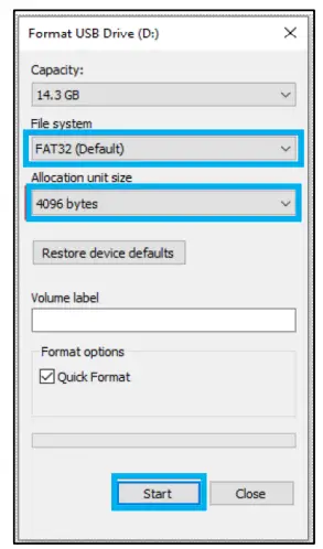 In file explorer, use the “Details” view and make sure “File name extension” is checked.
- Safely remove the USB flash drive from the computer.
- Power off the inverter.
- Insert the USB flash drive into the USB port on the inverter’s communications board as shown in the image.

- After the USB flash drive has been connected, power on the inverter.
- The inverter will display a loading screen for 3 – 5 minutes.
- After the LCD display resets, navigate to: Settings →Device info. → LCD version to confirm that the LCD display was updated properly.

TROUBLESHOOTING
10.1 FRONT PANEL LEDS
The front panel LEDs represent the working status for each port or group of ports. When an individual port is operating normally, it will have a solid green LED. If there is a fault, the port with the fault will have a flashing green LED. When a firmware update is taking place, all the port LEDs will flash with a green LED.

LED Fault Indicators:
| PORT | LED | STATUS |
| GRID | Blink every 100 ms | Load overcurrent |
| GEN | Blink every 100 ms | Generator overcurrent |
| HYBRID | Blink every 100 ms | EPS load overcurrent Parallel RSD alarm is triggered Inverter is running old firmware Inverter stops outputting |
| Blink every 500 ms | CAN communication cable is disconnected | |
| AC CP | Blink every 100 ms | AC couple port cannot be closed |
| SP1 – SP4 | Blink every 100 ms | Smart port overcurrent Smart port 4 trigger NEC PCS protection |
10.2 FAULT CODES
| FAULT CODE | INFO | DESCRIPTION |
| E000 | Model Fault | The model of inverter is faulty. |
| E002 | Overload | Overload in system. |
| E003 | Short Current | Short Current in system. |
| E004 | Inverter firmware mismatch | Inverter firmware mismatch with GridBOSS |
| E005 | NEC protection | Exceeded the NEC 120% rule. |
| E006 | Grid OCP | Overcurrent protection on grid port. |
| E007 | NBC Load OCP | Overcurrent protection non-backup load port |
| E008 | Gen OCP | Overcurrent protection on gen port |
| E009 | BC Load OCP | Overcurrent protection on backup load port |
| E010 | SM port1 OCP | Overcurrent protection on smart port1 |
| E011 | SM port2 OCP | Overcurrent protection on smart port2 |
| E012 | SM port3 OCP | Overcurrent protection on smart port3 |
| E013 | SM por4 OCP | Overcurrent protection on smart port4 |
10.3 WARNING CODES
| WARNING CODE | INFO | DESCRIPTION |
| W006 | RSD comm fault | Parallel system RSD communication error |
| W015 | Trip by Gen Freq or Voltage abnormal | Alarm due to generator frequency and voltage exceeding the range. |
| W016 | Trip by no Vac out of range | AC voltage out of range |
| W017 | Trip by Vac abnormal | AC voltage is abnormal |
| W018 | Trip by Fac abnormal | AC frequency out of range |
10.4 INTERNAL FUSE REPLACEMENT
GridBOSS contains two internal fuses that protect the unit from overcurrent situations. There is a fuse for line 1 and the second fuse is for line 2. If a fuse needs to be replaced, follow the steps listed below. Before starting the replacement procedure, be sure to locate the two extra fuses that shipped with the GridBOSS.

![]() DANGER:
DANGER:
Before working on the unit, verify all breakers are in the off position and there is no voltage/current at each breaker and lug connection point.
- The front inner black cable box cover must be removed to obtain access to the fuse area. Open the front door by releasing the three clasps on the right side of the unit. Next, remove the four screws as identified in the image below and then carefully remove the inner black cable box cover by lifting it out of the chassis.
- Remove the internal orange cover by first removing the two nuts using a 7mm socket and the four screws using a Phillips screwdriver. Then lift the cover out of the unit.

- Locate the two internal fuses outlined in blue in the image below.

- Remove the M6 screws (2 per fuse) as indicated by the blue arrows. Then remove each fuse.

- Set the new fuse in place. Verify the direction of the fuse matches the image below. The smaller notch open to side should be towards the grid input and the longer notch open on the end should be towards the inside of the chassis.

- Reinstall the four M6 screws and tighten to 80 in-lbs. (9.0Nm). NOTE: Verify the plastic insulator is positioned between the two fuses before securing them in place.

- Reinstall the orange inner cover plate removed in step 2.
- Reinstall the inner black cable box cover that was removed in step 1.
- The system is now be ready for use.
CHANGELOG
01-02-25
- Published v1.1.5
- Modified wording in Section 5.5 p.23 Generator Port. Value changed from 3% to 12%.
- Changed the shipping hybrid port breaker to 90A
- Removed requirement for shared battery when using more than one inverter with GridBOSS.
- Added fault and warning codes to section 10.
11-26-24
- Published v1.1.4
- Modified cover image to reflect new coat and logo
11-18-24
- Published v1.1.3
- Modified the relays and jump over line in the GridBOSS product overview and configuration examples diagrams.
- Added steps to replace the internal fuses under section 10.2.
- Changed mounting angle images in section 5.1.
- Changed recommended torque specification for the 30A – 125A breakers.
- Changed Product Overview into a main section, added labeling of chassis features.
- Added information that Dry 2 contacts are reserved and unused at this time.
- Updated smart load and AC coupling configuration information in sections 6 and 8.
- Added off-grid configuration example in section 6.1.
- Updated Monitor Center main page image to reflect Monitor Center update.
- Added idle consumption and transfer time data.
- Corrected link for the QR code on the front page.
- Added ground and neutral torque settings.
- Updated minimum FW for inverters when connected to GridBOSS
- Updated GridBOSS enable settings and image in section 5.6
- Added torque wrench to recommended tools list
10-31-24
- Published v1.1.2
- Modified spec sheet FCC Part 15, Class B to read as (pending)
- Modified formatting throughout document
- Added suggestion for users follow UL514B when installing unit in section 5.1
- Added breaker sizes included in shipment to section 5.4
- Added table describing breaker use-cases to section 5.4
- Added nominal knockout sizing table to section 5.4
- Added additional spacing information in section 5.1
- Added additional component compatibility for smart ports 3/4 in section 5.4
- Modified section numbering
10-16-24
- Updated specifications table to include hybrid breaker sizes and unsupported inverter note.
- Added breaker installation section.
10-15-24
- Initial document release
NOTES
![]()
CONTACT US
support@eg4electronics.com
903-609-1988
www.eg4electronics.com
Documents / Resources
 | EG4 GRIDBOSS Microgrid Interconnect Device [pdf] User Manual GRIDBOSS Microgrid Interconnect Device, GRIDBOSS, Microgrid Interconnect Device, Interconnect Device, Device |