![]() EMUBCAMKIT Universal Quad View Camera Kit
EMUBCAMKIT Universal Quad View Camera Kit
Installation Guide
UNIVERSAL QUAD VIEW CAMERA KIT with DVR
Important
![]() Please read and follow the instructions carefully. To emphasize special information, the symbol, and the words Warning, Caution and Note have special meanings. Pay special attention to messages highlighted by these signal words.
Please read and follow the instructions carefully. To emphasize special information, the symbol, and the words Warning, Caution and Note have special meanings. Pay special attention to messages highlighted by these signal words.
These instructions are designed as a guide to help make the installation of this product successful.
Always use caution and ask for assistance if you are not sure how to proceed.
AAMP Global & EchoMaster are not responsible for any damage that may occur during installation or any changes to the vehicle interior.
![]() WARNING
WARNING
Indicates a potential hazard that could result in death or serious injury![]() CAUTION
CAUTION
Indicates a potential hazard that could result in vehicle damage
NOTE
Indicates special information to make installation easier or instructions clearer.
Vehicle Preparation & Protection
CAUTION
Consult your vehicle owner’s manual to disconnect the battery. Do not disconnect ANY airbag connectors or indicators. Doing so may result in activating a diagnostic code. These codes will require the dealer to perform the reset procedure which may incur a reset fee. If you are unsure of any vehicle trim removal process consult the OEM service manual.
Removing vehicle trim panels in extremely hot and/or cold climates could result in damage. Use care when removing all vehicle trims. Using painter’s blue tape on the vehicle trim panels can help limit any scratches and/or marring. Use a nylon trim panel removal tool whenever possible.
NOTE
Consult the Vehicle owner’s guide before disconnecting the negative battery cable![]() WARNING
WARNING
DO NOT TOUCH the positive terminal with any tool when removing the negative battery cable
What’s in the box

| Image | Description | Qty |
| 1 | IR/Display Mode Harness | 1 |
| 2 | Camera Extension Cable | 4 |
| 3 | Camera Input Adapter | 4 |
| 4 | Interface Power/Trigger Harness | 1 |
| 5 | IR Remote Control | 1 |
| 6 | Power Switch | 1 |
| 7 | AVS-21 Harness | 1 |
| 8 | Video Output Harness | 1 |
| 9 | AVS-21 Video Switcher | 1 |
| 10 | Camera/Video Interface | 1 |
| 11 | AHD Cameras | 1 |
| 12 | USB Cable | 4 |
| 13 | Mount screw | 4 |
| 14 | RCA cable | 1 |
Recommended Tools
| Plastic Trim Tool | Diagonal Cutters | Utility Knife |
| Socket Set | Wire Crimpers | Drill |
| Ratchet | Electrical Tape | Brill Bits |
| Screwdrivers | Wire Feeder | |
Installation Notes
Read this installation guide thoroughly before disassembling the vehicle or making wire connections.
Installation of this product requires technical skill, experience, and specialized tools. If unsure, it is recommended to have it professionally installed by an authorized EchoMaster Dealer.
Questions?
Reach out to our Technical Support Team:
Phone: 727-592-5991
Email: support@aampglobal.com
Chat: EchoMaster.com
Camera/Video Interface Layout


EMUBCAMKIT
Universal Quad View Camera Kit
Step 1
Select a location for the Camera/Video Interface. Behind the glove box or below the radio are both good locations. Ideally, the location should be within two feet of the monitor being used. Run the USB extension to the desired position to access the USB port for DVR recordings. Once all the connections are made, the two-sided tape can be used to secure the module or you can secure it with screws.
Step 2
Select a location for the Display Mode Switch and IR Receiver. The Display Mode Switch should be easily reached by the driver. The IR Receiver should be in the general area of where the IR Remote Control will be used. Mount both the switch and the IR Receiver. Route the wire harness to the video interface and plug it in the appropriate port.

Step 3
Positioning The Cameras:
The cameras can be placed anywhere; wheel wells, frames, bumpers, and axles. Facing in any direction; forward, rearward, sideways.
Note: The cameras come with a mounting bracket at the top of the camera (FIG A). If your application requires mounting cameras with the bracket at the bottom of the camera (FIG B), the mounting bracket will need to be moved from the top holes in the camera housing to the bottom holes so the camera image is not upside-down.
A good idea is to temporarily position the cameras in the areas you would like to view (FIG C), route the camera cables to the video interface, wire up the system, and view the camera views on the monitor. With the help of another person, you can fine-tune the camera view before permanently mounting the cameras.
Mounting The Cameras:
The cameras should be mounted in positions that will not come in contact with the terrain or moving parts of the vehicle. The cameras must be mounted using both the two-sided tape and then screws or zip ties. Clean the mounting area before adhering the camera in place. 
Step 4
Routing The Camera Cables:
Attach a Camera Extension Cable to each camera and route the camera cables to the video interface inside the vehicle. Follow the factory wiring harnesses whenever possible.
Secure with zip ties. Most vehicles will have rubber grommets located in the floor that will allow the cables to be safely passed from the outside to the inside.
NOTE
Adding a piece tape and notating the camera position on the ends of the Camera Extension Cables will make identification inside the vehicle easier.
Step 5
For each camera; plug in a Camera Input
Adapter (1) into the video interface camera input. Align the arrows on the Camera Input
Adapter and Camera Extension Cable (2) and connect the cables.
Step 6
DIP switches 1-2-3-4 on the side of the module correspond to Camera Inputs 1-2-3-4. For any camera that is facing toward the rear of the vehicle, set the DIP switch to the ON (UP) position. This will “mirror” the video so it is viewed correctly on the monitor.
DIP switch 5 and 6 set the Video Output Type: See page 15 for setting video output once the unit is installed.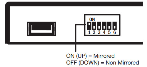
Wiring Guide
There are several different ways to connect the video interface to your monitor source. We have included several Wiring Diagrams. NOTE: If you are connecting to an after-market radio, you may need to remove the radio or refer to the radio owner’s manual to determine how to wire the video interface.
All installations require the power/ground connections in Step 1 below. After that, proceed to the Wiring Diagram that best matches your installation.
Step 1
On the 8-pin Power/Trigger plug:
A- Connect the Black wire to Ground
B- Connect the Red wire to Accessory +12V. (A source that turns ON-OFF with the key)
C- Connect the Yellow Wire to Constant +12V 
NOTE
If installed in a vehicle with an after-market radio, the power/ground connections can be made behind the radio.
Wiring Guide 1
Follow these instructions if you are connecting to:
- Stand-alone monitor
- After-market radio with Rear camera input, No rear camera installed, and On-screen option to turn on camera.
- After-market Radio with two or more camera inputs (with one of them not being used) and an On-screen option to turn on the camera.
Step 1
Plug the Video Output Harness into the video interface.
Step 2
Connect either the CVBS or AHD RCA to the Video IN on the monitor. If the monitor does not specifically say Analog High Definition, use CVBS. Insulate the red and blue wires.
OR
Connect either the CVBS or AHD RCA to the Rear Camera IN on the After-market radio. If the radio does not specifically say Analog High Definition, use CVBS.
Insulate the red and blue wires.
Test Set DIP switch 5 to the OFF (DOWN) position. Turn the key on. Power up the monitor or radio. Select the correct input on the monitor, or select the correct camera on the radio. See page 15 for setting video output.

Wiring Guide 2
Follow these instructions if you are connecting to:
- After-market radio with Rear camera input, a rear camera installed, and an On-screen option to turn on the camera
- Factory radio with a camera interface that can turn on the camera input manually.
This type of installation requires using the Power Switch and the PAC AVS-21 to switch the video signal between the rear camera and the video interface.
Step 1
Connect the Brown wire on the Power Switch to the Ground.
Step 2
Connect the Blue wire on the Power Switch to the Black wire on the AVS-21 harness.
Step 3
Connect the Red wire on the AVS-21 to Accessory +12V.
Note
The Power Switch needs to be reachable to switch the video signal from the rear camera to the video interface.
Step 4
Plug the Video Output Harness into the video interface.
Step 5
Connect either the CVBS or AHD RCA to the AV2 IN on the AVS-21. If the radio does not specifically say Analog High
Definition, use CVBS. Insulate the red and blue wires when not using.
Step 6
Unplug the rear camera RCA from the radios camera input and plug it into AV1 IN on the AVS-21.
Step 7
Plug the Yellow AV OUT RCA on the AVS-21 into the radio’s rear camera input.
Note
None of the white or red RCA’s on the AVS- 21 will be used.
Test
Set DIP switch 5 to the OFF (DOWN) position. Turn the key on. Power up the radio. Select the rear camera on the radio. You should see either the rear camera or the video interface. See page
15 for setting video output. Use the Power Switch to switch between the two 
Setting the Video Output
The video interface can output four different video signals: AHD 30 fps, AHD 25 fps, CVBS NTSC, and CVBS PAL. The default setting on the initial power-up is CVBS NTSC. To change the default video signal adjust the Dip switches to the chart on the right.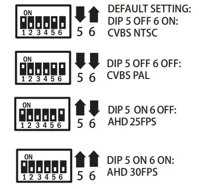
Trigger Wires
The four trigger wires on the 8-pin Power/Trigger plug can be used to manually activate each of the four cameras. When a trigger wire receives +12V, the corresponding camera will be displayed.
These can be connected to switches to instantly turn on a selected camera. 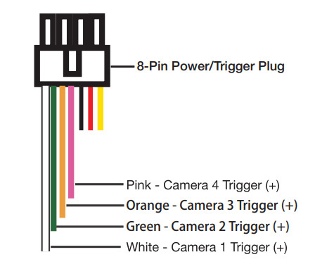
User Guide
IR Remote Control
When viewing the video interface, use the IR Remote control to switch between display modes and access Settings.
Display Mode Button
Pressing the Display Mode Button cycles through the various display modes.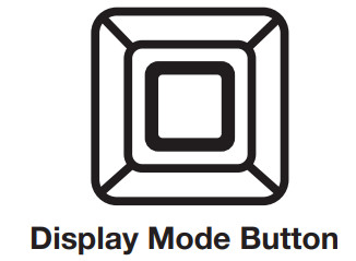
Display Modes
Along with full-screen modes for each camera, the video interface has different display modes that allow viewing multiple cameras at the same time. Change display modes via the IR Remote Control or the Display Mode Button. The last display mode viewed will be kept in memory when the vehicle is turned off.

Settings Menu
Pressing the MENU button on the IR Remote Control will bring up the Settings Menu. Use the arrows to navigate the settings icons. Press OK to select the highlighted icon. In the setting sub-menu, use the arrows to highlight or change the desired setting and then press OK to save and exit. 
| Loop Time Sets recording time for saved video files. 1 / 2 / 3 Minutes | |
| Display delay Sets display trigger time when using the Display Triggers to activate the source. 2 / 5 / 15 / 30 Seconds | |
| Video playback it records all 4 cameras on one screen Normal Video and SOS Video | |
| Language Sets the language displayed. Chinese(Simplified) / Chinese (Traditional) English / Korean | |
| Input Type Sets input video type/resolution. 720p 25fps / 720p 30fps / CVBS PAL / CVBS NTSC 720p 30fps recommended | |
| U-disk Output Type (Normal Video) = Recorded Percentage used on a storage device. (SOS Video) = Recorded Percentage used on a storage device. | |
| Clock Allows setting the time and date. This is important for time-stamping the recorded video files. | |
| Light freq Sets lighting frequency to reduce flicker. 50Hz / 60Hz | |
| Format Formats the Micro SD Card. This will erase any files on the card! | |
| Reset Resets setting to factory defaults | |
| Version Displays current firmware version. | |
| Return Select to exit the settings menu and return to the camera view. |
AGREEMENT: End user agrees to use this product in compliance with the instructions and terms of use above and with all State and Federal laws. EchoMaster provides instructions and safety warnings with respect to this product and disclaims all liability for any use not in conformity with those instructions or other misuse of its product. If you do not agree, please discontinue use immediately and contact EchoMaster. This product is intended for off-road use and passenger use only.
![]() 15500 Lightwave Drive, Suite 202, Clearwater, Florida 33760
15500 Lightwave Drive, Suite 202, Clearwater, Florida 33760
email – support@aampglobal.com
tel – 1-800-477-2267
EchoMaster is a Power Brand of AAMP Global.
EchoMaster.com
IG-EMUBCAMKIT
REV. 060822
Documents / Resources
 | ECHOMASTER EMUBCAMKIT Universal Quad View Camera Kit [pdf] Installation Guide EMUBCAMKIT, Universal Quad View Camera Kit, EMUBCAMKIT Universal Quad View Camera Kit, Quad View Camera Kit, View Camera Kit, Camera Kit |


