DMP 712-8INT Zone Expansion Module

DESCRIPTION
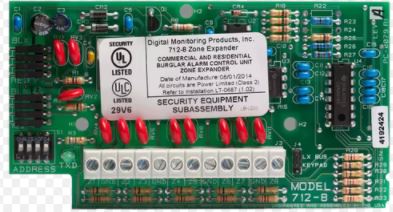
The Model 712‑8INT Zone Expansion Module allows you to increase the number of protection zones available on a DMP panel. The 712‑8INT provides a total of eight grounded zones.
The zone expansion module provides a terminal strip for zone inputs, two 4‑pin headers for Keypad Bus or LX‑Bus connections, a jumper for LX‑Bus or Keypad Bus operation, and a transmit data LED to indicate panel communication.
Note: The 712‑8INT is listed for use in burglary applications only: No fire circuits shall be used on this device.
Compatibility
- XT30INT/XT50INT Series panels
- XR150INT/XR550INT Series panels
What is Included?
- One 712‑8INT Zone Expansion Module
- Eight 1K Ohm EOL resistors
MOUNT THE MODULE
The module can be mounted in a DMP enclosure using the standard 3‑hole mounting pattern. Refer to Figure 2 as needed during installation.
- Hold the plastic standoffs against the inside of the enclosure side wall.
- Insert the included Phillips head screws from the outside of the enclosure into the standoffs. Tighten the screws.
- Carefully snap the module onto the standoffs.

WIRE THE MODULE
Use 18 to 22 gauge wire to connect the 712‑8INT directly to the Keypad Bus or use a dual‑ended 4‑wire harness to connect directly to the LX‑Bus. This connection allows the module to communicate with the panel and receive 12 VDC power. For more information about wiring, refer to Wiring Specifications. Refer to Figure 3 when wiring the module.
Connect to the LX‑Bus
- Place a jumper across the top two KEYPAD/LX‑ BUS pins.
- Connect one end of a 4‑wire harness to the top header on the module.
- At the panel, connect the other end of the 4‑wire harness to the LX‑Bus.
Connect to the Keypad Bus
- Place a jumper across the bottom two KEYPAD/LX‑ BUS pins.
- Connect a 4‑wire harness to the top header on the module.
- At the panel, connect the wires to the corresponding Keypad Bus terminals.

ADDRESS THE MODULE
To communicate the status of the eight zones, the module responds to two addresses on the Keypad Bus and eight addresses on the LX‑Bus. You can set the module starting address to any bus address from 0 to 15. The module automatically responds to this address, the next address on the Keypad Bus, and the next seven addresses on the LX‑Bus.
To change the current address, move the slide switches to the appropriate address positions according to Figure 4.
Keypad Bus Addressing
The module can be set to the following keypad addresses according to panel model: 1 through 8 for XT30INT/XT50INT and XR150INT Series panels, or 1 through 15 for XR550INT Series panels.
Additionally, the eight zones on the module occupy two keypad addresses.
For example, if the module is set to address 2, the first four expansion zones occupy address 2 and respond as zones 21‑24. The last four expansion zones occupy address 3 and respond to the panel as zones 31‑34. For more information about Keypad Bus addressing, refer to Table 1.
Note: Because the 712‑8INT is supervised, both addresses must be selected in Device Setup of the XR150INT/XR550INT Series programming when used on the Keypad Bus.
LX‑Bus Addressing
When connecting to the LX‑Bus, the module must be addressed to match the last two digits of the first zone being used. The next seven zone addresses are automatically used to communicate expander zones 2 through 8 status.
For example, on an XR150INT panel using LX‑Bus 1 if you set the module address to 8, the eight zones on the expander respond as zones 508 to 515. When connected to an XR550INT panel using LX‑Bus 2, the zones respond as 608 to 615. For more information about LX‑Bus addressing, refer to Table 2.
Note: Only two 712‑8INT Modules can be connected to each LX‑Bus.
Table 1: Keypad Bus Addresses
| DMP PANEL KEYPAD BUS | 712-8INT ADDRESS | EXPANDER ZONES 1-4 5-8 | |
| PANEL ZONES | |||
| XT30INT/ XT50INT Series, XR150INT/ XR550INT Series | 1 | 11‑14 | 21‑24 |
| 2 | 21‑24 | 31‑34 | |
| 3 | 31‑34 | 41‑44 | |
| 4 | 41‑44 | 51‑54 | |
| XT30INT/ XT50INT Series, XR150INT/ XR550INT Series | 5 | 51‑54 | 61‑64 |
| 6 | 61‑64 | 71‑74 | |
| 7 | 71‑74 | 81‑84 | |
| 8 | 81‑84 | 91‑94 | |
|
XR550INT Series | 9 | 91‑94 | 101‑104 |
| 10 | 101‑104 | 111‑114 | |
| 11 | 111‑114 | 121‑124 | |
| 12 | 121‑124 | 131‑134 | |
| 13 | 131‑134 | 141‑144 | |
| 14 | 141‑144 | 151‑154 | |
| 15 | 151‑154 | 161‑164 | |
Table 2: LX-Bus Addresse
| 712-8INT ADDRESS | XR150/XR550 SERIES LX-BUS | ||||
| PANEL ZONE RANGE | |||||
| LX-BUS 1 | LX-BUS 2 | LX-BUS 3 | LX-BUS 4 | LX-BUS 5 | |
| 0 | 500‑507 | 600‑607 | 700‑707 | 800‑807 | 900‑907 |
| 1 | 501‑508 | 601‑608 | 701‑708 | 801‑808 | 901‑908 |
| 2 | 502‑509 | 602‑609 | 702‑709 | 802‑809 | 902‑909 |
| … | … | … | … | … | … |
| 7 | 507‑514 | 607‑614 | 707‑714 | 807‑814 | 907‑914 |
| 8 | 508‑515 | 608‑615 | 708‑715 | 808‑815 | 908‑915 |
| 9 | 509‑516 | 609‑616 | 709‑716 | 809‑816 | 909‑916 |
| … | … | … | … | … | … |
| 12 | 512‑519 | 612‑619 | 712‑719 | 812‑819 | 912‑919 |
| 13 | 513‑520 | 613‑620 | 713‑720 | 813‑820 | 913‑920 |
| 14 | 514‑521 | 614‑621 | 714‑721 | 814‑821 | 914‑921 |
| 15 | 515‑522 | 615‑622 | 715‑722 | 815‑822 | 915‑922 |
ADDITIONAL INFORMATION
Wiring Specifications
DMP recommends using 18 or 22 AWG for all LX‑Bus and Keypad Bus connections. The maximum wire distance between any module and the DMP Keypad Bus or LX‑Bus circuit is 10 feet. To increase the wiring distance, install an auxiliary power supply, such as a DMP Model 505‑12. Maximum voltage drop between a panel or auxiliary power supply and any device is 2.0 VDC. If the voltage at any device is less than the required level, add an auxiliary power supply at the end of the circuit.
To maintain auxiliary power integrity when using 22‑gauge wire on Keypad Bus circuits, do not exceed 500 feet. When using 18‑gauge wire, do not exceed 1,000 feet. Maximum distance for any bus circuit is 2,500 feet regardless of wire gauge. Each 2,500 foot bus circuit supports a maximum of 40 LX‑Bus devices.
For additional information refer to the LX‑Bus/Keypad Bus Wiring Application Note (LT‑2031) and the 710 Bus Splitter/Repeater Module Installation Guide (LT‑0310).
Connecting to Other Modules
Using a 4‑wire connector as an extension of the Keypad Bus or LX‑Bus, you can easily connect the 712‑8INT to multiple modules on the same bus. Observe wire colors when making connections. For more information about wiring connections, refer to Figure 3.
Data LED
The LED on the 712‑8INT flashes each time the module responds to a poll from the panel. If there is a problem with the panel, system programming, or the connection between the panel and module, the LED stops flashing and a system trouble message displays on the keypad.
712-8INT ZONE EXPANSION MODULE
Specifications
Operating Voltage 8.0 to 14.5 VDC
Current Draw
Normal 17 mA + 1.6 mA per active zone
Alarm 17 mA + 2.0 mA per active zone
Dimensions 11.43 cm W x 5.08 cm H 4.50” W x 2.50” H
Weight 23 kg (8.0 oz)
Compatibility
XT30INT/XT50INT Series panels
XR150INT/XR550INT Series panels
Certifications

Designed, engineered, and manufactured in Springfield, MO using U.S. and global components.
LT-0687INT 1.01 20021
2500 North Partnership Boulevard
Springfield, Missouri 65803-8877
417.831.9362 | DMP.com
Documents / Resources
 | DMP 712-8INT Zone Expansion Module [pdf] Installation Guide 712-8INT, Zone Expansion Module |


