![]() BODYGUARD-T
BODYGUARD-T
Presence sensor w/monitoring
BODYGUARD-T Presence Sensor With Monitoring
Visit website for available languages of this document.
 https://www.qrfy.com/RlI5G4f4bB
DESCRIPTION

- End caps
- Lenses
- Center eye shield
- LED
TECHNICAL SPECIFICATIONS
| Installation height (variable): | 9’ 0” maximum (recommended: 6’ 6” – 8’ 0”) |
| Mounting angles Bodyguard-T only: Boydguard-T w/Bodymount: | 5°, 10° (factory default setting: 5°) 0°, 5°, 10° |
| Power supply: | 12 – 24 VAC / VDC ±10% |
| Monitoring request input: | 12 – 30 VDC required (polarity-sensitive) min. pulse width: 10 ms (active low) |
| Frequency: | 50 – 60 Hz |
| Output: | max. voltage at contacts: 60 VDC / 125 VAC max. current at contacts: 1 A max. switching power: 30 W (DC), 60 VA (AC) |
| Relay hold time: | 0.5 – 9 seconds |
| Operating temperature: | -22 – 140 °F |
| Immunity: | Immune to electrical and radio frequency interference |
| Cable length: | 4’ |
| Weight: | 1 lb 11 oz (765 g) |
| Dimensions: | 12” (W) x 2” (H) x 2” (D) (300.35 mm x 49.50 mm x 48.00 mm) |
| Material: | Aluminum and ABS plastic |
| Housing color: | Black, anodized aluminum |
Specifications are subject to change without prior notice. All values measured in specific conditions.
For more information, please visit www.devancocanada.com or call toll free at 1-855-931-3334
INSTALLATION TIPS
- The sensor should be mounted securely to avoid extreme vibrations.
- The sensor should be mounted above the door on the swing side.
- The sensor should be mounted flush with bottom of door header.
- Do not cover the sensor.
- Avoid moving objects and light sources in the detection field.
SINGLE-DOOR APPLICATIONS:
Sensor must be mounted at center of door opening.
If this is not possible, the unit may be installed off-center. Pattern location must be altered for proper detection field placement (see PATTERNS section). Avoid potentially problematic mounting locations (e.g. directly over a door arm). DUAL-EGRESS APPLICATIONS:
One sensor should be mounted over each swing path, with at least 40″ of separation between the two (measured from midpoint of each sensor). SIMULTANEOUS PAIR APPLICATIONS:
Sensor must be mounted at center of door opening.  Per ANSI 156.10:
When the Bodyguard-T is prevented from providing a safety signal to the control during the closing cycle, an additional sensor, sensors, or photo beam shall be used on the swing side to stop the door, or continue to close the door, or slow the reopening. For new installations of power operated door systems all presence sensors used for safety shall be monitored whereas existing installations using presence sensors for safety may be monitored, and monitoring is not mandatory.
SAFETY
- The door control unit and the header cover profile must be correctly grounded.
- Only trained and qualified personnel are recommended for installation and set-up of the sensor.
- Following installation, always test for proper operation (according to ANSI 156.10) before leaving the premises.
- The warranty is invalid if unauthorized repairs are made or attempted by unauthorized personnel.
MECHANICAL INSTALLATION
BODYMOUNT INSTALLATION
Bodymounts are required for Bodyguard-T installations with one or both of the following circumstances:
- reveal (i.e. distance from door face to Bodyguard mounting surface) is less than 3 inches
- SuperScan-T is also used
Disregard this sub-section and proceed to “Sensor Preparation” if a Bodymount is not required for this application.
- Apply the Bodymount mounting template to the desired location.
- Drill pilot holes for mounting and wire passage.
- Partially drill the 2 mounting screws into the pilot holes.
- Remove the left end cap of the Bodymount for wiring harness routing.
- Slide extrusion over mounting screws and hand-tighten the screws to secure to the block
 SENSOR PREPARATION
Remove both end caps from the sensor by unscrewing each Phillips head screw. Slide out each lens at its respective end of the sensor.
 Pull out the center eye shield from the top, while rotating out. Do this carefully, to avoid damage to the light tube on the inner side of the shield.
  Slide the PCB out of the extrusion and set aside.
 SENSOR INSTALLATION
MOUNTING DIRECTLY TO DOOR FRAME/HEADER:
- Align the sensor with the chosen location and attach the sensor using the two self-drilling screws (provided with kit). A pilot hole in the header may be necessary to ease screw installation.

- If the sensor is mounted directly to the header and the cabling will pass directly through the header, drill a 1⁄ 2″ wire passage hole next to the left-side end cap. Ensure that the hole location aligns with the end cap cut-out.
MOUNTING TO BODYMOUNT:
- Route harness through wire passage hole while aligning the sensor with the Bodymount.

- Attach the sensor to the Bodymount using the two self-drilling screws (provided with the kit).
REPLACE THE CIRCUIT BOARD: - Slide the circuit board back into the extrusion.

ANGLE ADJUSTMENTS:
Make any necessary angle adjustments after installation. Use the images below to aid in choosing angles.
Angles must match for each clip on the same PCB. Should only be used when the sensor is mounted to a Bodymount block or soffit above the door that extends out from the face of the safety side of the door. This would improve the detection field location across the threshold area of the doorway.
 For most applications, it is recommended that the unit be powered and walk-tested at this angle. After walk-testing, the detection field may be altered by adjusting the angle (see directions below).
WIRING
![]() Shut off all power going to the header before attempting any wiring procedures.
Shut off all power going to the header before attempting any wiring procedures.
WIRING TO MONITORED DOOR CONTROLS
- Plug the 10-pin connector to the Bodyguard-T using the provided cable. DO NOT USE the 7-pin terminal – this is not designed to be used with monitored systems.
Also verify that the monitoring DIP switch is set to ON. - Hard-wire to the door control. Reference the table below for connection points.
 WIRING TO NON-MONITORED DOOR CONTROLS
- Plug the 10-pin connector to the Bodyguard-T using the provided cable (without terminating the monitoring wires) OR hard-wire using the 7-pin terminal.
Also verify that the monitoring DIP switch is set to OFF. - Hard-wire to the door control. Reference the table below for connection points.
 10-PIN CONNECTOR (hard-wire connections)
| Position | Connection | Wire Color | Position | Connection | Wire Color |
| 1 | 12 – 24 VAC/VDC ±10% | BLACK | 6 | Normally Closed | YELLOW |
| 2 | 12 – 24 VAC/VDC ±10% | RED | 7 | Monitoring (+) | PURPLE/YELLOW |
| 3 | Common | WHITE | 8 | Monitoring (-) | PURPLE |
| 4 | Normally Open | GREEN | 9 | Data (+) | BLUE |
| 5 | 10 | Data (-) | BROWN |
WIRING TO MODULES
If wiring the Bodyguard-T to a BEA module (e.g. LO21, MC15), refer to the respective schematic for the module.
Monitoring may not be used if wiring to a BEA module; therefore, the DIP switch must be switched off.
Once wired, feed the free end of the cable through the wire passage hole (page 3, step 8), and into the header.
Pull the cable completely through and route it to the location of the automatic door control.
Refer to the respective User’s Guide for the BEA product with which you are interfacing.
Ensure a dedicated power source of 12 or 24 VAC / VDC ±10% (1024VAC may be used for powering this product).
MONITORING DIP SWITCH POSITION
The monitoring DIP switch is in the OFF position by default.
![]() Replace lenses, eye shield, and end caps before proceeding.
Replace lenses, eye shield, and end caps before proceeding.
POWER-UP
With the door in the closed position, apply 12 – 24 VAC / VDC ±10% to the sensor. LED will flash green until set-up is successful in “door closed” position 1. Activate the door to the “fully open” position. LED will flash green again and the sensor will execute a “door open” set-up.
 NOTES:
- If the door control requires a Learn cycle upon powering, it is recommended to allow the doors to complete a Learn cycle before applying power to the sensor.
HELPFUL HINT #1 (when using a lockout module)
During step 2 above, if during the first “open” cycle, the sensor does not begin flashing once door is fully open, a data problem is highly likely – if the door opened and the LED remained red (in detection), it probably did not receive the correct data signal from the respective lockout module or a control’s data circuit.
TRY THIS:
white wire on lockout OR negative data connection on control ![]() brown wire on Bodyguard-T red/white wire on lockout OR positive data connection on control
brown wire on Bodyguard-T red/white wire on lockout OR positive data connection on control ![]() blue wire on Bodyguard-T
blue wire on Bodyguard-T
TRY THIS:
check motor voltage (red and black on lockout OR control’s data circuit) has at least 10 VDC
HELPFUL HINT #2 (when using a lockout module)
After step 2 above, if the door achieves the “open“ position and set-up is successful but the door begins to close and recycles, it is possible that the sensor is detecting the closing door.
TRY THIS:
Check DIP switch 6 – should be ON if using a lockout (Besam Swingmaster MP (with CUP control) may require OFF position)
TRY THIS:
red wire on lockout ![]() positive leg on motor black wire on lockout
positive leg on motor black wire on lockout ![]() negative leg on motor
negative leg on motor
PROGRAMMING THE SENSOR
REMOTE CONTROL SET-UP
ALL functions are programmable using the remote control.
Use of the remote control should be within 10 – 15 feet of the sensor.
“Door Closed” and “Door Open” patterns are independently adjustable. It is necessary to adjust the pattern for a closed door, and then to adjust the pattern again when the door is open. The following functions may be independently adjusted for each door position:
- Sensitivity
- Pattern width
- Pattern depth
The following functions apply to both “Door Closed” and “Door Open” positions:
- Auto-Learn time
- Immunity (“medium” and “high” affect interpretation of objects in detection field relative to background; Learn time is unaffected)
- Frequency
- Output configuration
- Door control mode
- Hold time
- Interface type

| SET-UP |  | |||||||||||||||
| NUMBER KEYS (0 – 9) assign value for given function |  | |||||||||||||||
| INTERFACE 1: New Style 2: LO21 – Old Style (LO21B/K/P/S/U, LO-LINX, MC15, DP-HUB) | ||||||||||||||||
| DOOR CONTROL 1: Normal (LED in normal mode) 2: Door permanently open (red LED on) 3: Door permanently closed (red LED off) | ||||||||||||||||
| UNLOCK / INQUIRE / LOCK To UNLOCK the sensor: Press UNLOCK key once. Red LED flashes slowly. If flashing fast, see Note below. To LOCK the sensor: Press LOCK key twice OR press once, then enter a 4-digit lock code. If less than 4 digits, press lock again after the last digit. LED goes out when complete. To INQUIRE the sensor: Unlock sensor, press desired function key, then press INQUIRY key – number of green flashes corresponds to the value. NOTE: If sensor is locked, and code is unknown, power sensor off and then back on. Press UNLOCK key within 60 seconds. Re-lock with 0000 (default code). Sensor will unlock with one press of UNLOCK key when set to 0000. |  | |||||||||||||||
| MODES OF OPERATION 0: Normal 1: MP Mode 2: Record Mode | ||||||||||||||||
INFRARED FREQUENCY
See Quiet Mode note on next page. |  |
| Immunity | Output Config | Auto-Learn Time |
 | ||
| Sensitivity | Pattern Width | Pattern Depth |
 | ||
| Hold Time | ||
see next page for specific parameter settings
Specific Parameter Settings
| PARAMETER | SETTING |
| Sensitivity | 0 (min) default 7 = door open default 6 = door closed |
| Hold Time | 0 (0.5 s) |
| Output Configuration | 1: Normally Open Relay 2: Normally Closed Relay |
| Auto-Learn Time | 0: 30 seconds 1: 1 minute 2: 2 minutes 3: 3 minutes 4: 5 minutes 5: 7 minutes 6: 10 minutes 7: 15 minutes 8: 10 seonds 9: Infinity (no learn) |
| Pattern Width | 1: Wide (closed door) 2: Middle (open door) 3: Asymm. left narrow 4: Asymm. right narrow 5: Narrow left 6: Narrow right 7: Asymm. left wide 8: Asymm. right wide 9: Center narrow |
| See notes below for Pattern Width or Depth. | |
| Pattern Depth | 1: Deep – threshold ON 2: Medium – threshold ON (open) 3: Limited – threshold ON 4: Deep – threshold OFF 5: Medium – threshold OFF (closed 6: Limited – threshold OFF |
| See notes below for Pattern Width, Pattern Depth, and Threshold. | |
| Immunity | 1: Low (normal) 2: Medium – Rain (disregards more floor disturbances) 3: High – Snow (disregards greatest floor disturbances) |
| For BOYDGUARD-TC functionality, set Immunity to High. | |
| Set-up | |
| See Automatic Set-up note. |
NOTES:
QUIET MODE: The QUIET mode uses a different pulsing pattern to avoid interference with other infrared systems. The NORMAL mode transmits more energy and detects in a slightly crisper fashion.
PATTERN WIDTH & DEPTH: When pattern width or depth is changed, a set-up of the new pattern size will automatically be triggered once a value key has been pressed.
THRESHOLD: The Threshold is always OFF when the door is closed.
AUTOMATIC SET-UP: When performing an automatic set-up (set-up key pressed twice), the sensor will begin to flash green during the door-closed position, and will continue to do so until the door is activated to the open position. The LED will then go out and the door will close. The LED will flash green again at the closed position until a set-up is complete. Upon the next activation, the sensor will launch another set-up for the open-door position, and will begin normal operation thereafter.
Reducing Cross-Talk in Dual-Egress Applications
- Ensure that the two sensors are installed with < 40″ of separation between the two (measured from midpoint of each sensor).
- Place doors in Hold Open position. Unlock the sensor and set open door Pattern Depth to 5 (medium pattern). IR threshold will be off while in this door position. Be sure to change the setting on BOTH sensors.
- Change IR frequency on one sensor.
- If in an application with high-gloss floors or multiple doors installed in vestibules, change to different frequency.
PUSH-BUTTON SET-UP
Only the following functions are programmable using push-buttons:
- Sensitivity
- Output configuration
- Auto-learn time
- Pattern width
- Pattern depth
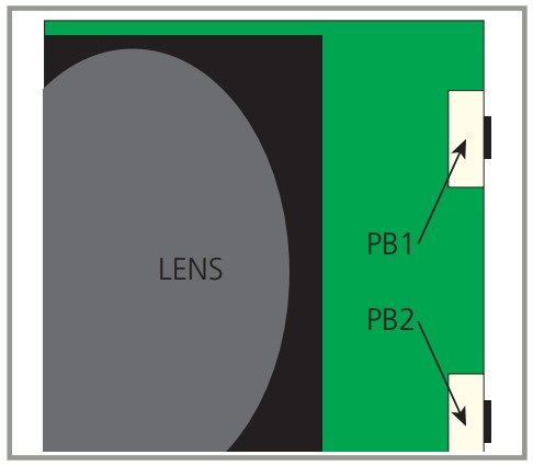
- Press PB1 for less than 2 seconds. LED will flash green for 10 seconds and the sensor will execute the appropriate set-up for the current door position. The green LED flashes at a slower rate if interruptions are detected in the field. Press PB1 to re-launch.
- Press PB1 for more than 2 seconds to change the parameters.
- To choose the parameter, press either PB1 or PB2, and the LED will flash red (indicating the parameter) and then flash a specific number of green blinks (indicating the current parameter setting). See chart below for reference.
NOTES:
* Pressing PB1 will toggle between parameters.
* Pressing PB2 will toggle between range of adjustments for that particular parameter.
* The value returns to the lowest setting when PB2 is pressed again after reaching the highest adjustment.
* Zero value = no LED flash
* To exit, wait 20 seconds or press PB1 for more than 2 seconds. - When finished with manual set-up, replace the right end cap.
| Red LED Status | Parameter | Description | Green LED Status |
| 1 flash | 1 | Sensitivity (door open) | 0 – 9 flashes (default = 7) |
| 2 flashes | 2 | Sensitivity (door closed) | 0 – 9 flashes (default = 6) |
| 3 flashes | 3 | Output configuration | 1 – 2 flashes (default = 1) |
| 4 flashes | 4 | Auto-Learn time | 0 – 9 flashes (default = 0) |
| 5 flashes | 5 | Pattern width (door open) | 0 – 9 flashes (default = 2) |
| 6 flashes | 6 | Pattern width (door closed) | 0 – 9 flashes (default = 1) |
| 7 flashes | 7 | Pattern depth (door open) | 1 – 6 flashes (default = 1) |
| 8 flashes | 8 | Pattern depth (door closed) | 1 – 6 flashes (default = 1) |
WIDTH & DEPTH PATTERNS
(all pattern sizes are approximations)
When the sensor is mounted at 7 feet high, each block in the charts shown represents 14″ x 14″.
Always walk-test the pattern to ensure compliance with all applicable standards.
 WIDTH PATTERNS
 ![]()
 DEPTH PATTERNS
 ![]()
Row 1 (spots 1 – 6) remain on even during the “closed-door” position.
TROUBLESHOOTING
| Sensor will not set up upon intial powering | Improper input voltage | Check terminals 1 and 2 for proper voltage (12 – 24 VAC / VDC ± 10%). |
| Sensor is in detection | Ensure field of detection is clear during set-up and all lenses are installed on sensor. If detection is encountered upon initial setup, the Bodyguard will continuously flash green at ±2 Hz. | |
| Permanent stationary objects are extremely close to the sensor. Ensure that the detection field clear and the sensor is mounted properly (using the Bodyguard mounting block if necessary). | ||
| Potential interferences from high-intensity lighting | Ensure no high-intensity lighting is in the immediate area of the sensor. | |
| Change to a different frequency. | ||
| Data type mismatch (old/new) | Verify that the data matches type LO21 or EDPS. | |
| Door will not open once set-up is complete | Sensor is in detection (red LED is on) | Verify no changes in detection field made since set-up. If permanent changes have occurred, launch a new set-up and re-test door (CAUTION: THERE MAY BE NO SAFETY ON THE DOOR WHEN THIS TEST IS PERFORMED). |
| Improper wiring | Remove output wires from the sensor. For controls using N.C. circuits, twist together the relay wires. Activate the door control. If the door opens, the fault exists with sensor or related wiring. If door does not open, the fault may exist with the door control or its related wiring. | |
| Safety beams are in detection | Disconnect green and blue wires from LO21 to the door control safety and common terminals. If door opens when triggered, fault lies within the lockout safety beam set, or possibly with the LO21. Refer to the LO21 troubleshooting procedures in the respective manual. | |
| Improper relay output configuration | Ensure proper relay output setting. | |
| Sensor repeatedly re-Learns environment with each door position | Improper data from lockout device | 1) Allow door to open in automatic mode. Unlock sensor and launch a set-up by pressing the Set-Up key, followed by the number 2. If the sensor LED returns to red and does not begin flashing green, improper data exists. 2) If unsuccessful, allow the door to close. Unlock sensor and launch a set-up by pressing the Set-Up key, followed by the number 2. If the sensor LED flashes green, the lockout module needs replaced. Refer to respective lockout User’s Guide for troubleshooting. |
| Data polarity at sensor is incorrect | Verify that the negative wire from the lockout (white) is connected to terminal 6, and the red/white wire from the lockout is connected at terminal 7. HELPFUL HINT: If faulty data is suspected, simply power the door to the open position (by activation OR with the use of a “hold open” switch). While the door is open, unlock the sensor and press the Set-Up key, followed by the number 2. If the sensor LED returns to red and does not begin flashing green, improper data exists. Refer to respective lockout User’s Guide for troubleshooting. | |
| Sensor is not reacting to remote control | RC batteries are dead | Replace batteries. |
| Too much distance between sensor and RC | Move closer to sensor during programming. | |
| Data type mismatch (old/new) | Verify data matches type LO21 or EDPS. | |
| Unknown | Attempt manual programming procedure (page 7). HELPFUL HINT: Use Spotfinder to test RC output. | |
| Visible Monitoring Indication LED does not flash | Monitoring installation /set-up error | Verify monitoring is active in door control (active low). |
| Sensor malfunction | Replace sensor. | |
| Monitoring DIP switch is OFF | Verify DIP switch poisiton (must be switched to the left). | |
| Visible Monitoring | Monitoring installation /set-up error | Verify door control is capable of monitoring and sensor monitoring wires are properly connected to control. |
| Wiring malfunction | Verify that there are no breaks anywhere in the wire harness. | |
| Door control does not utilize monitoring | Move monitoring DIP switch to the right (OFF) OR apply 12 – 30 VDC to the purple and purple/yellow wires (observe polarity). |
 https://www.qrfy.com/RlI5G4f4bB
Can’t find your answer? Visit www.beainc.com or scan QR code for Frequently Asked Questions!
BEA, INC. INSTALLATION/SERVICE COMPLIANCE EXPECTATIONS
BEA, Inc., the sensor manufacturer, cannot be held responsible for incorrect installations or incorrect adjustments of the sensor/device; therefore, BEA, Inc. does not guarantee any use of the sensor/device outside of its intended purpose.
BEA, Inc. strongly recommends that installation and service technicians be AAADM-certifi ed for pedestrian doors, IDA-certifi ed for doors/ gates, and factory-trained for the type of door/gate system.
Installers and service personnel are responsible for executing a risk assessment following each installation/service performed, ensuring that the sensor/device system performance is compliant with local, national, and international regulations, codes, and standards.
Once installation or service work is complete, a safety inspection of the door/gate shall be performed per the door/gate manufacturer’s recommendations and/or per AAADM/ANSI/DASMA guidelines (where applicable) for best industry practices. Safety inspections must be performed during each service call – examples of these safety inspections can be found on an AAADM safety information label (e.g. ANSI/DASMA 102, ANSI/DASMA 107, UL294, UL325, and International Building Code).
Verify that all appropriate industry signage, warning labels, and placards are in place.![]()
![]()
For more information, please visit www.devancocanada.com
or call toll free at 1-855-931-3334
Documents / Resources
 | Devanco Canada BODYGUARD-T Presence Sensor With Monitoring [pdf] Instruction Manual BODYGUARD-T Presence Sensor With Monitoring, BODYGUARD-T, Presence Sensor With Monitoring, Sensor With Monitoring, Monitoring |