1. Produktüberschreitungview
The SVBONY TransAir3 is a wireless HDMI transmitter and receiver system designed to extend 1080P@60Hz video signals up to 1000 feet (300 meters) in open areas. It features 9 auto-tuning 5.8GHz channels for stable connectivity, ultra-low latency of 0.06 seconds, and supports IR remote control. The receiver unit offers dual HDMI outputs for connecting two monitors, while the transmitter includes an HDMI loop-out port for local monitoring. This system is ideal for various applications including home entertainment, presentations, and video monitoring.

Image 1.1: SVBONY TransAir3 Wireless HDMI Extender system with its main features: 1080P 60fps, 1000FT Transmission Distance, 0.06s Low Latency, HDMI Loop Out & Dual HDMI Output, and IR Infrared Extension.
2. Packungsinhalt
Bitte überprüfen Sie, ob alle unten aufgeführten Artikel in Ihrem Paket enthalten sind. Sollten Artikel fehlen oder beschädigt sein, kontaktieren Sie bitte unseren Kundenservice.
- Transmitter (TX) Unit x 1
- Receiver (RX) Unit x 1
- Antennen x 4
- Type-C to USB Cable x 2
- IR Cables x 2
- Mini High Definition Multimedia Interface Adapter x 1
- Micro High Definition Multimedia Interface Adapter x 1
- High Definition Multimedia Interface Cable x 2
- Benutzerhandbuch x 1
Video 2.1: An unboxing video demonstrating the contents of the SVBONY TransAir3 package, including the transmitter, receiver, cables, adapters, and user manual.

Image 2.2: A visual representation of the package contents, including the transmitter, receiver, antennas, various cables, and adapters.
3. Komponentenidentifikation
Familiarize yourself with the ports and controls on both the transmitter (TX) and receiver (RX) units.
3.1 Sendereinheit (TX)
- Antennenanschlüsse: For connecting the external antennas.
- Infrared Interface: For connecting the IR transmitter cable.
- Data Interface (HDMI Input): Connects to your source device (e.g., STB, PC, DVD).
- Data Interface (HDMI Loop Out): Connects to a local display for simultaneous monitoring.
- Typ-C-Schnittstelle: Zur Stromversorgung.
- M6 Threaded Interface: Zur Montage von Zubehör.
- NP-F Battery Interface: For optional NP-F series battery power (battery not included).
- Stromschalter: Zum Ein-/Ausschalten des Geräts.
- Pairing-Taste: Press and hold for 5 seconds to initiate pairing.
- LED-Anzeige: Indicates battery status and signal connection.
3.2 Empfängereinheit (RX)
- Antennenanschlüsse: For connecting the external antennas.
- Infrared Interface: For connecting the IR receiver cable.
- Data Interface (HDMI Output 1 & 2): Connects to display devices (e.g., TV, monitor).
- Typ-C-Schnittstelle: Zur Stromversorgung.
- M6 Threaded Interface: Zur Montage von Zubehör.
- NP-F Battery Interface: For optional NP-F series battery power (battery not included).
- Stromschalter: Zum Ein-/Ausschalten des Geräts.
- Pairing-Taste: Press and hold for 5 seconds to initiate pairing.
- LED-Anzeige: Indicates battery status and signal connection.
Video 3.1: A detailed view of the transmitter and receiver units, highlighting their various interfaces and ports for connection and power.

Bild 3.2: Nahaufnahme view of the transmitter's side panel, detailing the Infrared Interface, Data Interfaces (HDMI In/Loop Out), and Type-C power port.

Bild 3.3: Nahaufnahme view of the receiver's side panel, detailing the Infrared Interface, Data Interfaces (HDMI Outputs), and Type-C power port.

Image 3.4: Illustration of the M6 threaded interface for mounting and the NP-F battery interface for portable power options.

Image 3.5: Detail of the side panel showing the power switch and the pairing button (press and hold for 5 seconds).

Image 3.6: The LED display on the unit, which shows battery power status (solid blue for >20% or stable connection, blinking for <20% or signal loss).
4. Einrichtungsanweisungen
The TransAir3 system is designed for plug-and-play operation and is factory-paired for immediate use. Follow these steps for initial setup:
- Antennen anschließen: Screw the four included antennas onto the antenna ports of both the transmitter (TX) and receiver (RX) units.
- Stromversorgung der Einheiten: Connect the Type-C to USB cables to the Type-C interfaces on both the TX and RX units, then connect the USB ends to appropriate power sources (e.g., USB wall adapter, computer USB port). Alternatively, install optional NP-F series batteries (not included) into the battery interfaces.
- Connect Transmitter to Source: Connect an HDMI cable from your video source device (e.g., STB, PC, DVD player) to the HDMI Input port on the TX unit. If desired, connect a local display to the HDMI Loop Out port on the TX unit for simultaneous monitoring.
- Connect Receiver to Display: Connect an HDMI cable from the RX unit's HDMI Output port (or both HDMI Output ports for dual monitors) to your display device(s) (e.g., TV, monitor, projector).
- Einschalten: Turn on both the TX and RX units using their respective power switches. The units should automatically connect.
- Verbindung überprüfen: Check the LED display on both units. A solid blue light indicates a stable connection. If the light is blinking, refer to the troubleshooting section.

Image 4.1: A visual guide to the plug-and-play setup process: connecting the transmitter to a source, the receiver to a display, and confirming installation.
5. Bedienungsanleitung
5.1 Grundlegende Bedienung
- Once connected and powered on, the TransAir3 system will automatically establish a wireless link.
- Stellen Sie sicher, dass Ihr Anzeigegerät auf den richtigen HDMI-Eingang eingestellt ist.
- The system automatically switches to the most stable 5.8GHz channel to maintain an uninterrupted connection.
5.2 IR Remote Control Functionality
The TransAir3 supports IR pass-through, allowing you to control your source device remotely from the display location.
- Connect the IR transmitter cable to the Infrared Interface on the TX unit and position the IR emitter near the IR receiver of your source device.
- Connect the IR receiver cable to the Infrared Interface on the RX unit and position the IR receiver in a location where it can receive signals from your remote control.
- Use your source device's original remote control (not included) to operate the device from the display location.
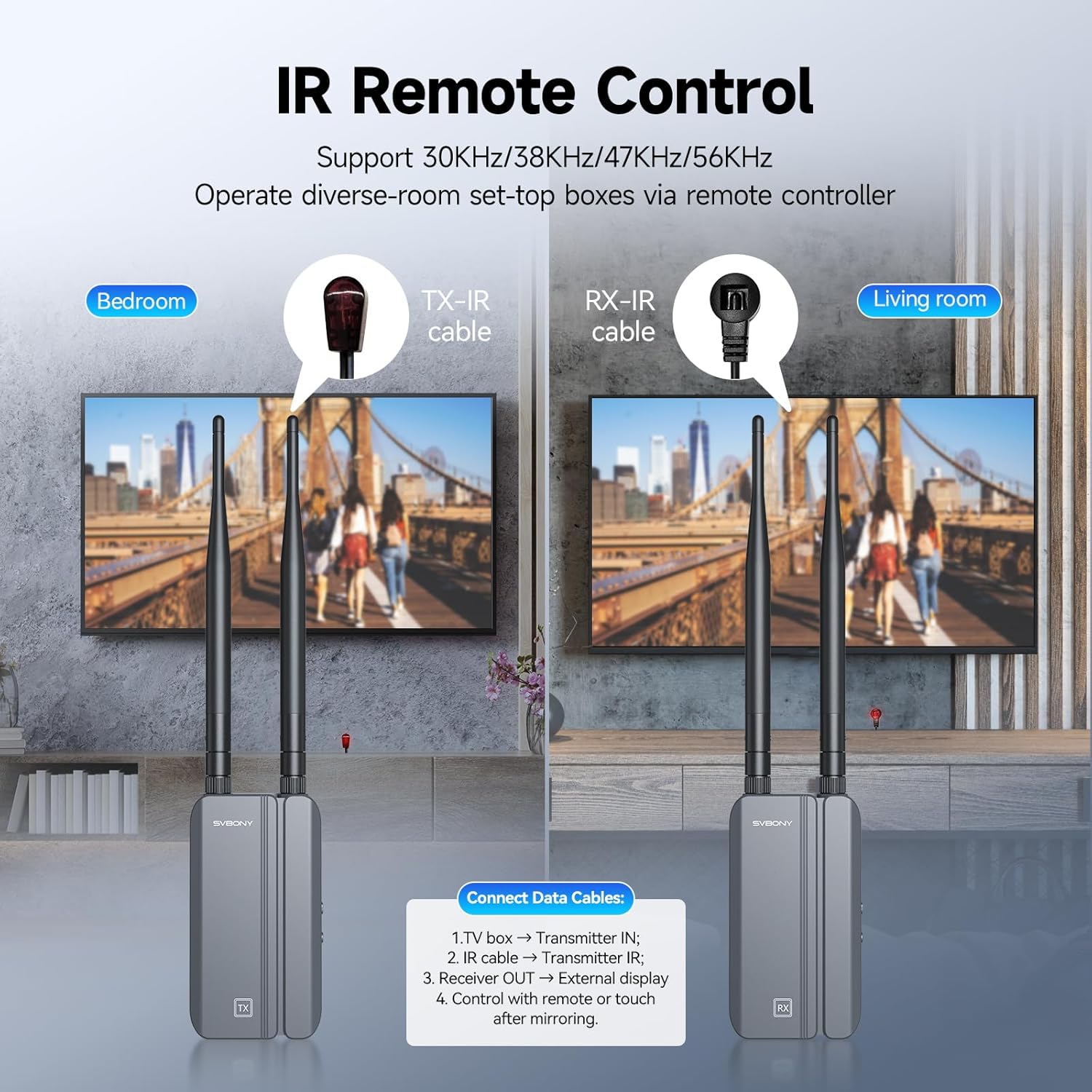
Image 5.1: Setup for IR remote control, showing the TX-IR cable connected to the source and the RX-IR cable positioned for remote signal reception.

Abbildung 5.2: Beispielample of using the infrared remote control feature to manage a source device from a different room.
5.3 Dual Monitor Output (RX Unit)
The receiver unit is equipped with two HDMI output ports, allowing you to connect and display the same video signal on two separate monitors simultaneously.
- Connect HDMI cables from both HDMI Output ports on the RX unit to your two desired display devices.
- Both displays will show the same content from the source device.
5.4 Multiple Receiver Support (Optional)
One transmitter (TX) unit can be paired with up to four receiver (RX) units (additional RX units sold separately) to broadcast the signal to multiple displays.

Image 5.3: Illustration of a single transmitter broadcasting to multiple receiver units and their connected displays.
6. Wartung
To ensure the longevity and optimal performance of your SVBONY TransAir3 system, follow these maintenance guidelines:
- Reinigung: Use a soft, dry cloth to clean the exterior of the units. Avoid using liquid cleaners or aerosols, which may damage the components.
- Belüftung: Ensure the units are placed in well-ventilated areas. Do not block the bottom air vents, as they are designed for heat dissipation.
- Lagerung: Bei längerer Nichtbenutzung sollten die Geräte an einem kühlen, trockenen Ort, geschützt vor direkter Sonneneinstrahlung und extremen Temperaturen, aufbewahrt werden.
- Kabelmanagement: Um Beschädigungen zu vermeiden, sollten Kabel nicht übermäßig gebogen oder gequetscht werden.

Image 6.1: The thermal design of the unit, highlighting the bottom air vents that facilitate heat dispersion for stable performance and extended service life.
7. Fehlerbehebung
If you encounter issues with your TransAir3 system, refer to the following common problems and solutions:
| Problem | Mögliche Ursache | Lösung |
|---|---|---|
| Kein Videosignal auf dem Bildschirm. |
|
|
| Video quality is poor or flickering. |
|
|
| Die Infrarot-Fernbedienung funktioniert nicht. |
|
|
| LED display is blinking blue. |
|
|
8. Spezifikationen
Technical specifications for the SVBONY TransAir3 Wireless HDMI Extender.
| Besonderheit | Detail |
|---|---|
| Modellnummer | TransAir3 |
| Videoauflösung | Bis zu 1080p bei 60 Hz |
| Übertragungsdistanz | Bis zu 300 Meter (1000 Fuß) in offenen Bereichen |
| Latenz | 0.06 Sekunden |
| Drahtlose Frequenz | 5.8GHz (9 auto-tuning channels) |
| Hardware-Schnittstelle | Radio Frequency, HDMI, Type-C, IR |
| Data Link-Protokoll | IEEE 802.11 |
| Stromversorgung | Type-C (external power supply) or NP-F batteries (not included) |
| Abmessungen (pro Einheit) | 2.5 x 1.18 x 4.56 Zoll (64 x 29 x 116 mm) |
| Gewicht (pro Einheit) | Ca. 0.9 kg |
| Farbe | Black + Gray |
| Besondere Merkmale | HDMI Loop-Out, Dual HDMI Output, IR Remote Control, LED Status Display, Excellent Heat Dissipation |
9. Garantie und Support
SVBONY products are designed and manufactured to the highest quality standards. For warranty information, technical support, or service inquiries, please refer to the contact information provided in your product packaging or visit the official SVBONY webBitte bewahren Sie Ihren Kaufbeleg für Garantieansprüche auf.