1. Einleitung
Thank you for choosing the VDO 333707 Cockpit Royale Style Electronic Tachometer Gauge. This manual provides detailed instructions for the proper installation, operation, and maintenance of your new tachometer. Please read this manual thoroughly before installation and keep it for future reference. This electronic tachometer is designed for precise engine RPM measurement in various automotive and marine applications.
2. Sicherheitshinweise
- Vor Beginn jeglicher elektrischer Installationen muss immer die Fahrzeugbatterie abgeklemmt werden, um einen Stromschlag oder Schäden am elektrischen System des Fahrzeugs zu vermeiden.
- Stellen Sie sicher, dass alle Kabelverbindungen sicher und ordnungsgemäß isoliert sind, um Kurzschlüsse zu vermeiden.
- Mount the gauge securely to prevent it from becoming a projectile during sudden stops or impacts.
- Do not operate the vehicle while distracted by gauge installation or adjustments.
- Wenn Sie sich bei irgendeinem Teil des Installationsprozesses unsicher sind, wenden Sie sich an einen qualifizierten Kfz-Techniker.
3. Packungsinhalt
Bitte vergewissern Sie sich vor Beginn der Installation, dass alle Komponenten vorhanden sind:
- VDO 333707 Electronic Tachometer Gauge (3 1/8" Diameter)
- Montagehalterung und Hardware
- Wiring Harness/Connector
- Bedienungsanleitung (dieses Dokument)
4. Einrichtung und Installation
The VDO 333707 tachometer is designed for a standard 3 1/8" (approximately 80mm) mounting hole. Ensure you have adequate space behind the mounting surface for the gauge body and wiring connections.
4.1 Montage des Messgeräts
- Select a suitable location on your dashboard or panel that provides clear visibility and does not obstruct other controls.
- Cut a 3 1/8" (80mm) diameter hole using an appropriate hole saw. Deburr the edges of the hole.
- Insert the tachometer into the mounting hole from the front.
- From the rear of the panel, slide the mounting bracket over the threaded studs on the back of the gauge.
- Thread the retaining nuts onto the studs and tighten them evenly until the gauge is secure. Do not overtighten.
4.2 Kabelverbindungen
Refer to the wiring diagram provided with your specific gauge or consult the VDO official website for detailed diagrams. General wiring connections are as follows:
- Red Wire (+12V Switched Power): Connect to a switched 12-volt power source that is active when the ignition is on. This can typically be found at the fuse box or an accessory circuit.
- Schwarzer Draht (Masse): Connect to a good chassis ground point. Ensure the connection is clean and secure.
- Green/Blue Wire (Ignition Signal): Connect to the negative side of the ignition coil (for conventional ignition systems) or the tachometer output signal wire from the ECU/ignition module (for electronic ignition systems). Consult your vehicle's service manual for the correct tachometer signal wire location.
- White/Orange Wire (Illumination): Connect to the vehicle's dashboard lighting circuit. This will illuminate the gauge when your headlights are on.
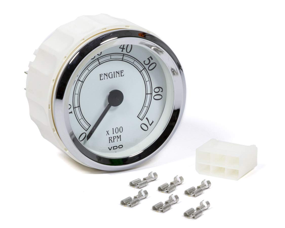
Image: VDO 333707 Cockpit Royale Style Electronic Tachometer Gauge. This image displays the front face of the gauge, featuring the RPM scale, needle, and classic VDO Cockpit Royale styling.
5. Bedienungsanleitung
Once properly installed and wired, the VDO 333707 tachometer operates automatically. When the vehicle's ignition is turned on, the gauge will power up. As the engine runs, the needle will indicate the engine's revolutions per minute (RPM). The gauge is designed to provide accurate and stable readings across its specified RPM range.
- Das Messgerät ablesen: The main scale indicates RPM in thousands. For example, '2' represents 2,000 RPM, '4' represents 4,000 RPM, and so on.
- Beleuchtung: The gauge's backlight will activate when the vehicle's dashboard lights are turned on, providing clear visibility in low-light conditions.
6. Wartung
The VDO 333707 tachometer is designed for long-term reliability with minimal maintenance. Follow these guidelines to ensure optimal performance and longevity:
- Reinigung: Reinigen Sie die Messfläche mit einem weichen, fusselfreien Tuch.amp cloth. Do not use abrasive cleaners or solvents, as these can damage the lens or finish.
- Inspektion: Periodically check all wiring connections to ensure they remain secure and free from corrosion. Inspect the mounting hardware for tightness.
- Umweltschutz: While designed for automotive environments, avoid exposing the gauge to extreme moisture or direct water spray.
7. Fehlerbehebung
If you experience issues with your VDO 333707 tachometer, refer to the following troubleshooting steps:
- Gauge Not Powering On/No Illumination:
- Check the +12V switched power (red wire) connection and ensure it has power when the ignition is on.
- Verify the ground (black wire) connection is secure and making good contact with the chassis.
- For illumination issues, check the illumination (white/orange wire) connection and the vehicle's dashboard lighting circuit.
- Tachometer Not Reading/Erratic Reading:
- Ensure the ignition signal (green/blue wire) is correctly connected to the appropriate signal source (ignition coil negative or ECU tach output).
- Check for loose or corroded connections in the signal wire.
- Verify the signal source is functioning correctly.
- Ensure the gauge is compatible with your vehicle's ignition system (e.g., 4, 6, 8 cylinder settings if applicable, though this model is typically self-adjusting or pre-set).
- Falsche Lesung:
- Confirm the signal wire is connected to the correct source and not picking up interference.
- Compare the reading with another known accurate tachometer if possible.
If these steps do not resolve the issue, contact VDO customer support for further assistance.
8. Spezifikationen
| Besonderheit | Spezifikation |
|---|---|
| Modellnummer | 333-707D |
| Messgerätetyp | Electronic Tachometer |
| Stil | Cockpit Royale |
| Durchmesser | 3 1/8 inches (approx. 80mm) |
| Eingangslautstärketage | 12 V Gleichstrom (Nennspannung) |
| Artikelgewicht | 272 g |
| Produktabmessungen (L x B x H) | 19.3 x 13.7 x 10.4 cm |
| UPC | 754059014470 |
9. Garantieinformationen
VDO products are manufactured to high-quality standards and are typically covered by a manufacturer's warranty against defects in materials and workmanship. The specific terms and duration of the warranty may vary by region and product. Please retain your proof of purchase. For detailed warranty information, including terms, conditions, and how to make a claim, please visit the official VDO website or contact VDO customer support directly.
10. Unterstützung
For technical assistance, troubleshooting beyond the scope of this manual, or warranty inquiries, please contact VDO customer support. You can typically find contact information, including phone numbers and email addresses, on the official VDO webSeite? ˅ (www.vdo-gauges.com or relevant regional VDO sites). When contacting support, please have your product model number (333-707D) and proof of purchase readily available.


