![]()
PTL-ST-1
SMART TERMINAL
REMOTE CONTROLLER
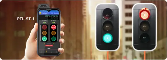

- RAISE TO WAKE
- CHANGE LIGHTS

- LOWER TO STANDBY
© 2025 Data Signs Pty Ltd. All rights reserved | UNCONTROLLED WHEN PRINTED | MAN 0011K Issue 1 | Rev: 14/04/2025
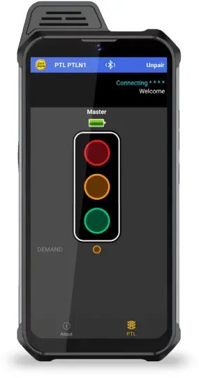
The ST-1 as a PTL Remote
Your PTL Remote is normally set to pair to the Master PTL on startup, or see ‘Switching ON and PAIRING the Remote’.
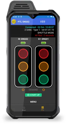
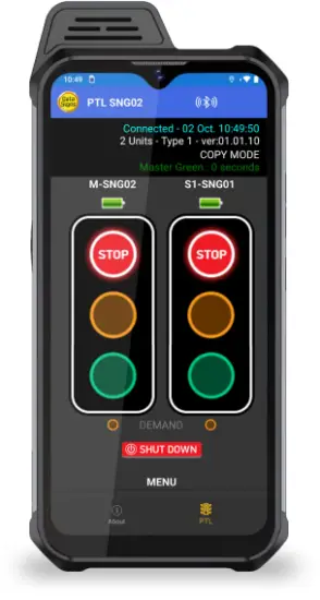
Status screen
The top line shows date and time, if this count is active your device is paired.
The second line shows how many units are connected. i.e. 2 Unit(s).
The third line shows the Mode the PTL is operating, i.e. SHUTTLE MODE.
The fourth line shows the remaining time for the phase.
THE MAIN SCREEN
The Main screen will display the lights for the Master on the left and the Slave on the right.
If in Gating mode only one PTL will be visible.
The battery level is shown above each light.
An Alarm will indicate if the battery reaches a ‘too low’ level and recharging is required.
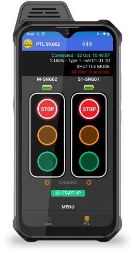
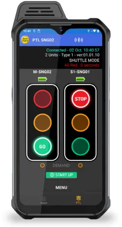
Tap the Red lamp to change to Red if the light is on Green.
When BOTH lights are Red, you can tap either Green to change that light to Green.
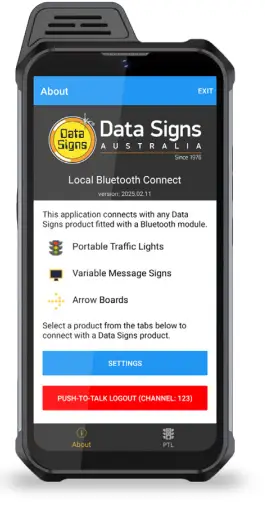
Switching ON and PAIRING the Remote
A Start-up page and sequence is displayed when the ST-1 is turned ON, this is done by pressing and holding the lower-right side button.
After the Startup sequence, press the ![]() button to start the Local Connect App.
button to start the Local Connect App.
Then select PTL tab ![]() from the tab at the bottom of the screen.
from the tab at the bottom of the screen.
To close the application, tap the ![]() button in the top-right corner or tap the square box in the bottom-right and swipe the application.
button in the top-right corner or tap the square box in the bottom-right and swipe the application.
Exiting the app will disconnect from all devices but the devices will continue their last operation.

- ON SWITCH
(on side of remote)
PRESS and HOLD
Pairing to the PTL continued…
To pair to the PTL, tap the PTL icon in the footer.

If Auto Connect is enabled in Settings, the ST1 will start scanning immediately.
If Auto Connect is not enabled, tap the ![]() button to begin scanning.
button to begin scanning.
Tap on the serial no. when it appears in the list. If Auto Connect is enabled, the remote will automatically connect with the last connected device if it is in range.
If the last connected device is not in range, the remote will continue scanning and will display all the relevant devices in range.
To stop automatically connecting with the last connected device, go to the Settings section and disable the Auto Connect option or tap the Clear Auto Connect Serial Nos button.
To stop scanning, tap the ![]() button.
button.
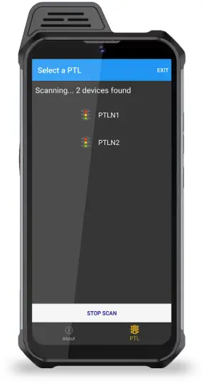
As the Bluetooth connection is established a progress sequence of 5-stars will appear, and the screen will redirect to the relevant remote screen.
To disconnect from a the PTL, tap the ![]() button in the top right corner.
button in the top right corner.
Disconnecting will stop the Bluetooth connection, but the PTL will continue its last operation.
SHUTTLE MODE
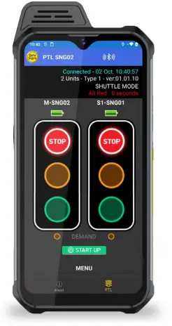
A demand for Green or Red signal on the Master or Slave is entered on the Remote Control unit. For Shuttle Control, on startup, both the Master and Slave will rest on Red until a demand for Green is entered.
To enter a demand for either Red or Green, tap the STOP or GO buttons on the Remote Control. The DEMAND indicator is activated indicating a demand for either the Master or Slave.
You can directly select the GREEN for the opposite light: the lights will sequence through to the ALL RED sequence and then to the selected GREEN.
LIGHT CHANGE SEQUENCE EXAMPLE
Master Green Both Red Slave Green

REAR BEACON LAMP
The Beacon Lamps mounted behind the Traffic Lights flash on each unit when the Red Lights are ON. This is useful for the operator to know the Lamp is on RED phase when behind the actual lights. It also acts as a Caution indicator for Vehicles.
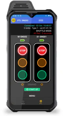
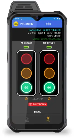
PLANT CROSSING (OR COPY MODE)
Plant-Crossing scenario is used to enable both directions of traffic flow along a roadway to be simultaneously stopped, e.g. to allow road construction vehicles (or pedestrians in a controlled environment) to cross.
On start-up, the Master is Red and the Slave copies this and is also RED.
The operator can enter a demand for Red signal using either STOP buttons on the Remote. Both the Master and Slave units will then cycle to Yellow and the Red signal phase.
To change back to Green signal, tap either the Master: GO or Slave: GO buttons.
Plant Crossing Control example:
- Both the Master and Slave are on Green.
- Tap either the Master: STOP or Slave: STOP buttons
- To resume traffic flow, tap either GO button.
To change the settings, tap the ![]() button at the bottom of the screen then tap on the Settings Menu button:
button at the bottom of the screen then tap on the Settings Menu button:
- Logging Enabled – enables logging to diagnose issues
- Auto Connect – will automatically connect with the last connected device
- Startup Tab – on startup; the app will jump to this tab directly and will start scanning.
- Clear Auto–Connect Serial Nos – will clear the list of last connected device serial numbers
- Clear Cache – will clear any locally cached data

Press-to-Talk Walkie Talkie
Push-To-Talk (PTT) is a new feature in DS-LCT that allows users to communicate with each other. PTT uses a special (orange) button on the ST-1 and requires internet access.
1. Log into DS-Live and go to the ![]() >
> ![]() section.
section.
2. Click on ![]() and setup a Secure Channel and Password.
and setup a Secure Channel and Password.

3. Open the DS-LCT app on your ST-1 and from the About tab, tap the “Push-To-Talk” button.
If internet access is required, a prompt will be displayed.


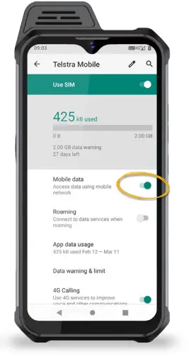
4. To enable internet access, insert a SIM card into the phone.
On the ST-1 home screen, swipe up and tap the Settings icon. 
Go to Network & Internet, tap Mobile Network and enable Mobile Data.

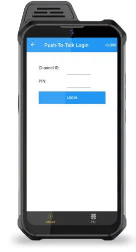
5. After connecting to the internet, tap the ![]() button and enter the agreed Secure Channel ID and PIN.
button and enter the agreed Secure Channel ID and PIN.
NOTE: devices that need to communicate with each other have to login on the same Secure Channel.
6. After connecting to a Secure Channel, push the orange PTT button on the ST-1 to communicate.
Battery and Charging the ST-1
The lithium Ion batteries MUST only ever be charged using the charger supplied by Data Signs. This charger must not be modified or used for any other purpose.
Handling
In the event a battery needs to be replaced please contact Data Signs. The lithium ion batteries are generally very reliable and replacement is unusual. It is possible there are other operational issues.
For full safe handling description download document from https://datasigns.com.au/ServiceSupport/HelpDesk
Glossary of Terms and Abbreviations
Aspects
The actual lights or housing that contains the Lights.
HRC
Hand-Held Radio Controller.
This term is interchangeable with PTL Remote.
Lights
Actual Traffic signal Lamps.
Red, Yellow and Green.
LiPo
Lithium Iron Phosphate.
A lightweight high energy density battery that powers the PTL.
Main PTL
Also as referred to as Master.
PTL
Portable Traffic Light.
PTL Remote
This term in interchangeable with HRC.
This is the Hand Held Remote that is used to control all the PTL Signal changes, control the Lights ON/OFF function as well as other functionality as described in this Manual.
PTSU
Portable Traffic Signal Unit.
This term is interchangeable with PTL.
Secondary PTL
Also referred to as Slave PTL.
Suggestions & Improvements
Data Signs develops its products with the end users in mind. As such, we are always open to suggestions for product improvement. Contact Data Signs, Head Office in Australia at: datasigns.com.au/help
Disclaimer
The information contained in this document is proprietary information of Data Signs Pty Ltd unless otherwise indicated. Data Signs Pty Ltd make every effort to ensure the quality of the information it makes available. Notwithstanding the foregoing, Data Signs Pty Ltd does not make any warranty as to the information contained herein and does not accept any liability for any injury, loss or damage of any kind incurred by use of or reliance upon the information.
Data Signs Pty Ltd reserves the right to make modifications, additions and deletions to this document at any time and without notice.
The Data Signs logo is a registered trademark of Data Signs Pty Ltd in Australia, New Zealand, United Kingdom, India and United States of America, and a trademark in other countries.
![]()
DATA SIGNS AUSTRALIA PTY LTD
APPENDIX A
Cycle and Phase Intervals for Shuttle and Plant Crossing Modes

- MASTER PHASE
- MASTER FLASHING BEACON
- MASTER SIGNAL DISPLAY
- SLAVE SIGNAL DISPLAY
- SLAVE FLASHING BEACON
- SLAVE PHASE

- GREEN PHASE
- MASTER FLASHING BEACON
- MASTER SIGNAL DISPLAY
- SLAVE SIGNAL DISPLAY
- SLAVE FLASHING BEACON
- RED PHASE
LEGEND: ![]() FLASHING Beacon
FLASHING Beacon ![]() YELLOW 4 seconds
YELLOW 4 seconds ![]()
![]()
![]()
PTL-ST-1 OPERATIONS MANUAL
Documents / Resources
 | Data Signs PTL-ST-1 Smart Terminal Remote Controller [pdf] Instruction Manual PTL-ST-1, PTL-ST-1 Smart Terminal Remote Controller, Smart Terminal Remote Controller, Terminal Remote Controller, Remote Controller, Controller |