Danfoss X-Gate Gateway Unit Type

Introduction
X-Gate is the new Danfoss gateway, designed to support and make the “Integration” activity at the field level. X-Gate can manage mainly two kinds of integrations:
- At the south-bound level: Capability to read from electronic devices with different protocols: Modbus RTU, Modbus TCP/IP, BACNet IP, BACNet MS/TP, CANBus and translate into another protocol suitable for the integration at the monitoring system level. Typical Modbus RTU.
- At the north-bound level: Capability to read the Open XML protocol from System Manager 800A and expose the normalized data points on different protocols: Modbus RTU or TCP/IP, BACnet IP for an “on top” BMS.
DISCLAIMER: Professional Use Only
This product is not subject to the UK PSTI regulation, as it is for supply to and use only by professionals with the necessary expertise and qualifications. Any misuse or improper handling may result in unintended consequences. By purchasing or using this product, you acknowledge and accept the professional-use-only nature of its application. Danfoss does not assume any liability for damages, injuries, or adverse consequences (“damage”) resulting from the incorrect or improper use of the product and you agree to indemnify Danfoss for any such damage resulting from your incorrect or improper use of the product.
Use Cases Scenarios
Following the typical use-cases scenarios where X-Gate can fit:
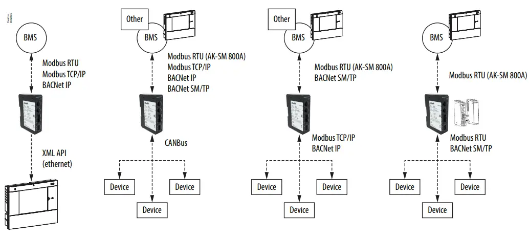
X-Gate can provide flexibility with a focus on 3rd party device integration into System Manager and at the same time make it easy for a BMS to integrate the desired data points over standard protocols.
First-time configuration
For the installation phase of X-Gate please refer to the standard “Installation Guide” provided inside the packaging. X-Gate has a Web User Interface, that can be accessed using a standard browser. The X-Gate starts in DHCP mode to be easily connected to an existing network. To discover the IP address of X-Gate in the network, the User can plug in a USB pen driver and perform the following steps:
On your PC:
- Insert a USB memory stick.
- Make sure the USB stick is formatted as FAT or FAT32.
- Create an empty file in the root named node_info.txt.
- Unmount and remove the USB memory stick from your PC.
On your X-Gate:
- Power-up the X-Gate
- Insert the USB stick into the USB connector of the X-Gate.
- Wait about 10 seconds (X-Gate will write the information in automatic mode into the txt file).
- Remove the USB stick and insert it into your PC
The file node_info.txt will contain the basic information about the X-Gate. Here is an example of the content:
- [node_info]
- ip=10.16.176.86
- mac_address=02:50:41:00:00:01
- sw_descr=X-Gate v.1.10 (180628.1713)
The file contains information on IP and aMAC-ADDRESS of X-Gate.
After getting the IP address of X-Gate in the network, the User can connect using a browser by typing the following URL: http://10.16.176.86 If you connect directly to X-Gate to PC via ethernet cable on ETH2, you will find the X-Gate at the IP address 192.168.2.101.
System Access
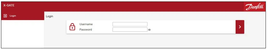
Login
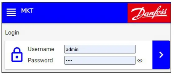
To access the main configuration section of X-Gate, a login is required with User & Password. The default account is “admin” with the default password “PASS”. For security reasons, after 3 attempts to enter a wrong password, X-Gate will lock access for 10 minutes. The default login credentials must be changed in the ser Configuration menu.
- After the first login, we strongly suggest changing the default password to prevent unauthorized access.
- After logging into the system, the User can access the configuration options according to the user profile.
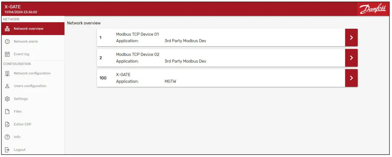
Network Overview
“Network Overview” is the landing page after login. It contains the list of the devices (Node) connected to X-Gate, plus the X-Gate itself.
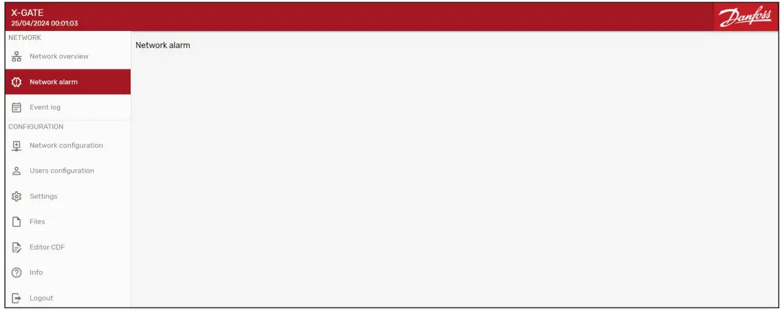
Network Alarm
The network Alarm page contains the real-time alarm list of the X-Gate device. It can be used to troubleshoot in case of problems in the installation.
If parameter “G17 Enable alarm history” is enabled, a history of cleared alarms and other events will be kept in X-Gate.
The following events are recorded:
- Alarm start/end.
- Alarm acknowledges.
- Power-up
- Change of parameter
- Firmware updates
- Time change
- Security threat
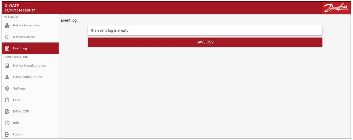
Event Log
The event page traces the events of the X-Gate. Users can save the event log list in a csv format.
User Configuration
User List
The accounts list can be accessed from the User Configuration page. By default, 4 users are available in the system: admin, Manufacturer, Service, and User.
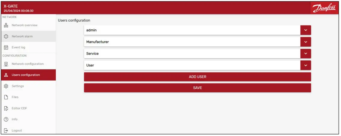
All the Accounthaveas have a dedicated profile to have different visibility inside the X-Gate configuration page. Profiles available are Maintenance and Service.
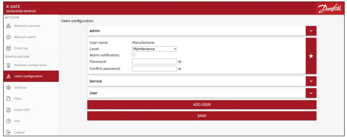
The User Configuration page provides the following features:
- “Add User” button: To add a new user to the system.
- Delete “—” button: to delete the single user.
- “Save” button: to confirm the modification done.
Network Configuration
Device List
The device (Node) list can be accessed from the Network Configuration page. The default Device present is the X-Gate itself with its configuration.

To add a new device, the “Add Node” button that provides the information needed:
- Node Id: the serial address of the device
- Description
- Application: the device profile with the list of the data points to read
- Protocol address: in the case of TCP/IP protocol like Modbus, it is the IP address of the device itself.
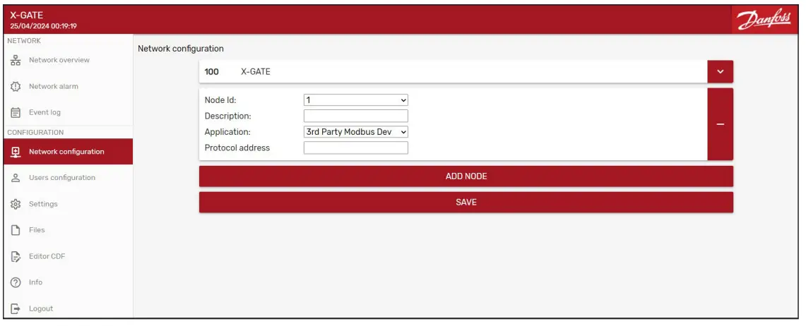
Every time the User adds or removes a device, he must be saved with the “Save” button.
X-Gate set-up
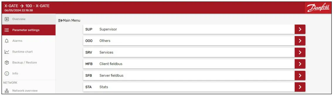
Enter the “Network Overview” and access the X-Gate main menu page.
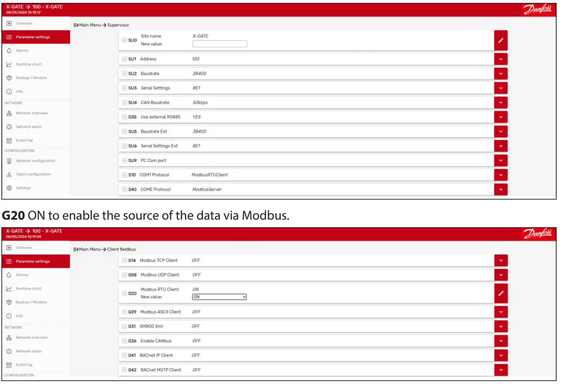
Supervisor
This page contains the main parameters to set up the communication over a serialrial line.
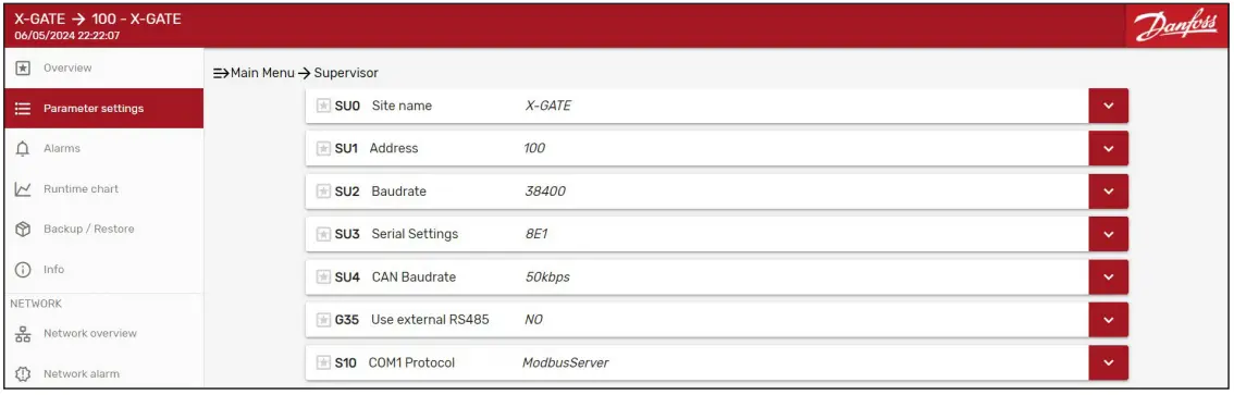
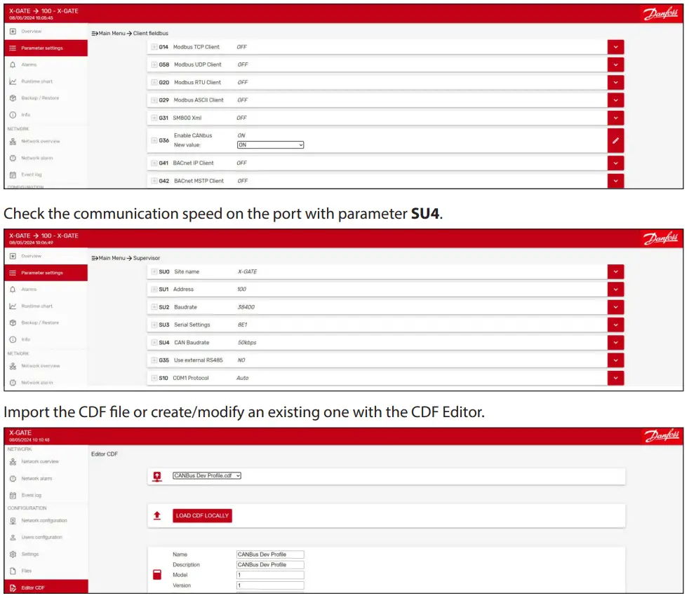
- SU2 & SU3 are the configuration parameters for the serial line at COM1.
- SU4 is used to set up the speed over the CANBus serial line (there is a dedicated port for CANBus built-in into X-Gate).
- S10 is used to define which protocol must be used on the COM1 serial port.
- In case of an extra RS485 module, parameter G35 must be put at YES.
- An extra set of parameters can be set up:
- SU5 & SU6 are the configuration parameters for the serial line at COME (COM Extension).
- S40 is used to define which protocol must be used for the COME (COM Extension) serial port.
Other
This page contains the main parameters to set up the LAN configuration both for the ethernet port 1 and port 2.
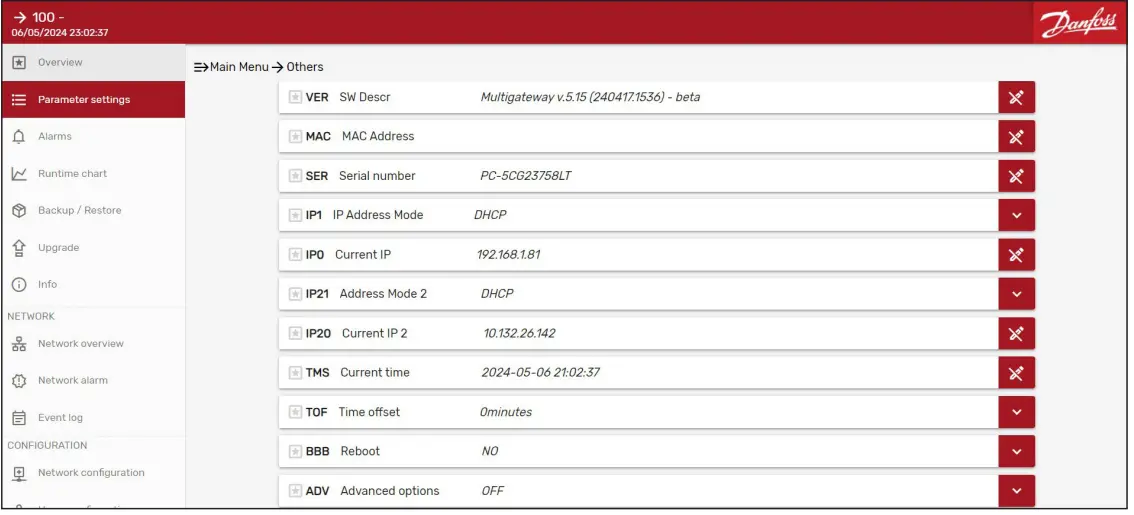
- In the case of STATIC IP management, set up parameters IP1 & IP21 to “Static”. BBB parameter can be used in case of a manual reboot of the X-Gate machine.
Services
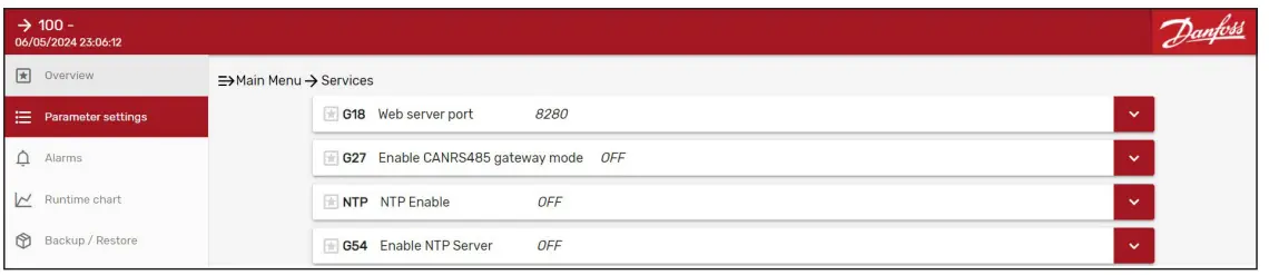
Parameter NTP will enable X-Gate to synchronize the time with an online service. Parameter G54 will enable X-Gate as an NTP Server for another Client.
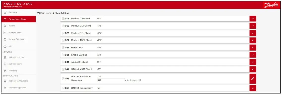
Client Fieldbus
This section allows configuring to the“SOURCE of the DATA”.
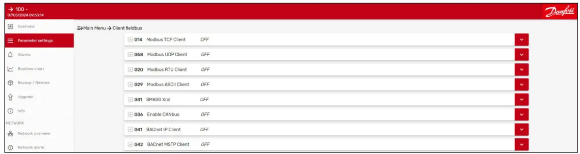
According to the protocol to read from the device on the field, the User must activate the right configuration.
- G14: To enable communication with Modbus TCP/IP device using the RJ45 (LAN) cable.
- G58, G20, G29: To enable the communication with Modbus device over the serial port (RS485).
- G31: To enable in case X-Gate must read over XML protocol on System Manager (via LAN cable).
- G36: To enable for a communication with a CANBus device.
- G41, G42: To enable in case of BBACnetdevice with IP (LAN) or MSTP over serial RS485.
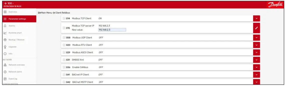
According to the enabled client fieldbus, extra configuration parameters will be displayed. Here is the example in the case of Modbus TCP/IP with the need to set up the IP address of the device.
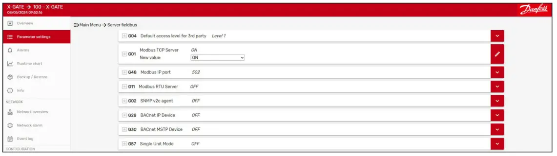
Server Fieldbus
This section allows to configuration of the “DESTINATION of the DATA” read from the field.
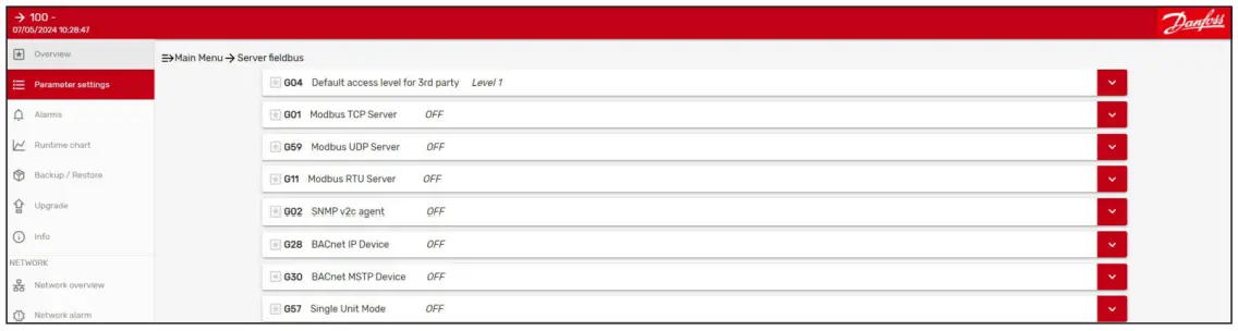
According to the protocol to read from the device on the field, the User must activate the right configuration.
- G01, G59: To enable the data sharing via Modbus TCP/IP server.
- G11: To enable the data sharing in Modbus on the RS45 port.
- G02: To enable data sharing over SNMP protocol over TCP/IP.
- G28, G30: To enable data sharing over BBACnetin IP or MSTP according to the settingAccording to the enabled server fieldbus, extra configuration parameters will be displayed. The G04 parameter provides the capabilityto limit variable visibility according to the Level. From Level 1 to Level 3. The level is a characteristic of the variable coming from the CDF file (or CDF Editor).
CDF Editor
The Editor CDF is a feature that allows the user to edit or create from scratch a CDF file. To use it, click on the “Editor CDF” icon on the left side of the menu tab.

The user can decide to load and eventually modify an existing CDF. If the desired CDF is stored inside the X-Gate, the “Select CDF from X-Gate” window must be opened.
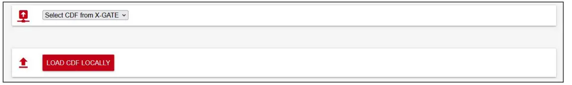
All the CDF files stored inside the device will be listed and are available for selection.

Either way, if the CDF is not stored inside the X-Gate itself but is saved inside the host machine (a PC, eventually), click on “LOAD CDF LOCALLY” and select the file you want to load.
Create new CDF
- If a CDF must be created from scratch, the user must fill in the CDF fields as described in the following sections.
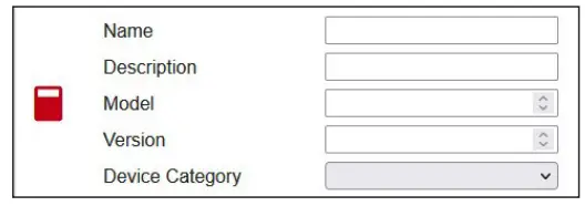
- The header of the CDF is a field that contains a general overview of the CDF itself. Five fields can be modified.
- Name: The given name will be stored inside the CDF and will also be the file name. It is a string oaof maximum of 20 characters. This file must be filled.
- Description: A general description of the CDF. It is a string ofa a maximum of 20 characters. This filemust be filled.
- Model: A 2 digitnumber, representing the model of the CDF. This field must be filled.
- Version: A 3 digitnumber, representing the version of the CDF. For example, if the field is 100, the version will be interpreted as 1.0.0. This field must be filled.
- Device Category: A list, containing the category of the CDF. It is an optional field.
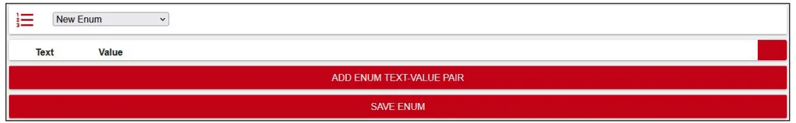
The enum section allows the user to create and modify new enumeration types.
If the button “ADD ENUM TEXT-VALUE PAIR” is clicked, an additional row will appear:
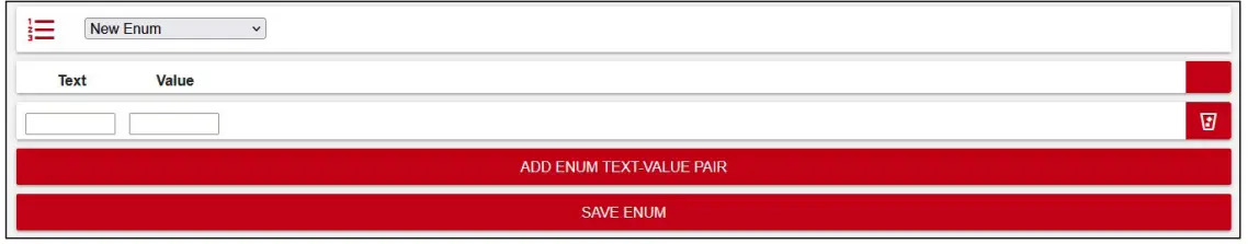
Two fields describe the text-value pair that needs to be added to the enumeration under definition:
- Text: A textual description of the current enumeration value
- Value: the relative value
For example, suppose that the user wants to define an enumeration representing the baud rate available for a serial communication:
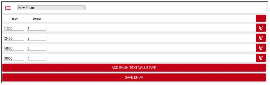
Once the enum is complete, the user must click “SAVE ENUM” to use it in the parameters section, which will be described later. All the defined enums will be saved inside the CDF. If the enum is correctly formatted, then a successful message will appear: “ENUM SAVED” message. Otherwise, if an error is presentwhen clicking on “SAVE ENUM” the corresponding row will appear highlighted in red:

In this case, the same text cannot be used for storing two different values. Once an enum has been correctly saved, the selection list containing all the enenumssill refresh and the jjust-createdentity will appear formatted as follows:

Where 13 is the index of the enum (this means that the CDF file already had 12 enum saved), followed by the texts used to define the enum itself. In case of error during the Enum creation, there are some conditions to look for asfollowsg:
- The text is not unique.
- The value is not unique.
- The value is not numeric.
The parameters table allows the user to specify the parameters that will be stored inside the CDF:
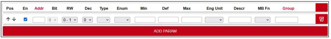
The fields that define a parameter are:
- Pos: Position inside the table. If the user clicks the arrows on the left of the rows, the parameter position will be switched with either the next or the previous parameter (if possible). This feature can be used for quickly sorting the file in case the parameter is out of place by some positions.
- En: If the En checkbox is selected, the device will be saved inside the groups and will be visible.
- Addr: Represents the address of the parameter (for example, the registered address for a Modbus register)
- Bit: This selection box is enabled and can be modified just for U1-typed parameters. It represents the bit that this parameter occupies for the given address.
- • RW: Read/Write permission. The first digit is relative to the read permission, the second is relative to the write.
- 0: always allowed
- 1: require level user
- 2: require level of service
- 3: require level OEM
- X: hidden
- Dec: Number of decimals, disabled if the parameter is of type STR or U1
- Type: The type of the parameter. Can be:
- Empty
- U1: Unsigned bit
- U8: Unsigned 1 byte
- U16: Unsigned 2 bytes
- U32: Unsigned 4 bytes
- U64: Unsigned 8 bytes
- S16: Signed 2 bytes
- S32: Signed 4 bytes
- S64: Signed 8 bytes
- F32: Float 4 bytes
- F64: Float 8 bytes
- Enum: This field can be either empty or one of the indexes of the defined enums
- Min: The minimum value that the parameter can assume
- Def: The default value that the parameter will assume.
- Max: The maximum value that the parameter will assume
- Eng Unit: The Engineering unit that describes the parameter.
- Descr: A textual description of the parameter
- MB Fn: In the case of Modbus protocol, the user can specify the function code used to interact with it
- Group: The group that contains the parameter. If this field is empty, then the group is “ROOT” by default. Otherwise, the group is the string provided by the user. The group can be nested inside another group with the “|” char. For example, the group “Stats | Calculated” defines the
- Calculated group inside the Stats group.
In the previous image, the “Addr” and “Group” column header are highlighted in red. If the user clicks them, the entire parameter table will be sorted in ascending/alphabetical order. This feature can be used to quickly sort a messy CDF.
Note: also a parameter row can be deleted from the table by clicking the bin icon located at the right of the group.
The following conditions are defined as errors when creating a new param:
- The addresss field is empty.
- The address field contains chars different from 0-9.
- The address field is not unique with respect to all other addresses.
- Min, default, and maximum are not coherent with the given parameter type (for example, max=256 and type=U8)
- Min <= default <= maximum is not respected
- Min, default ,,and maximum ccontainhars different from 0-9.
The alarms table allows the user to specify the alarms that will be stored inside the CDF:
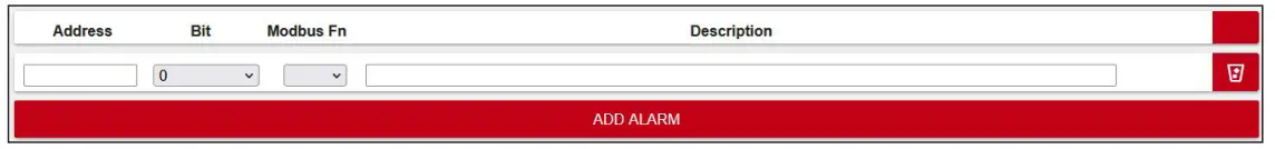
The fields that define an alarm are:
- Address: Represents the address of the alarm
- Bit: Represents the bit of the address which is effectively occupied by the alarm
- Modbus Fn: In the case of Modbus protocol, the user can specify the function code usedd to interact with it
- Description: A textual description of the parameter
The following conditions are defined aerrorssor when creating a new alarm:
- The pair (Address, Bit) is not unique.
- The tags table allows the user to link a pre-defined tag with a
- Parameter
- parameter list
- Enum
- Alarm list
- Enum reference
- Number
- Text
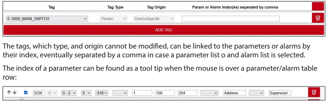
In the case pictured above, the index is seven. Note that the index of the first parameter is 0. The following conditions are definederrorsrror when creating a new tThe tag
- The tag is not unique.
- The tag type is “param” and more than one param aispecified.
- Tag type is “param”, “param list” or “alarm list” and the index(es) specified are higher than the index of the last defined param.
As for the loading part, the CDF can be either saved on the X-Gate itself or in the local host, such as the ususer’sC. The user must click one of the buttons pictured below, according to its necessity.
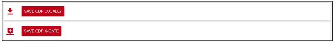
The button with the label “SAVE CDF LOCALLY” allows the user to save and store the edited CDF in the host (PC), while the other saves the CDF on the X-Gate itself. If the saving procedure does not find any error, then the file is either downloaded or a message saying “CDF saved on XGATE” will be shown. On the other side, if any error on the CDF file is found, an alert will pop up: “There are some errors: could not save the file”. The message shown above will appear if the save procedure finds one or more errors. The possible errors have been listed and explained in the previous sections. The user can then explore the CDF and see where the error is located, by searching for a red backgrounded element, such as is the following:

Once all the errors are resolved, the CDF can be saved again.
Note: that the errors are also shown in real time and not just when a CDF is saved. The row that was modified by the user is scanned when another row has been clicked.
8. Customization of HTTP user interface
It is possible to customize the user interface of X-Gate.
It is possible to customize the:
- Logo in the top right corner of the (instead of the default Danfoss logo)
- The color of the interface (instead of the default red)
Logo Customization
- To customize the logo shown at top right of the page, create a PNG file named custom_logo.png with width of 133 pixels, height of 55 pixels.
- Once the PNG file is ready go to the “Files” menu, which can be found on the left-side panel:
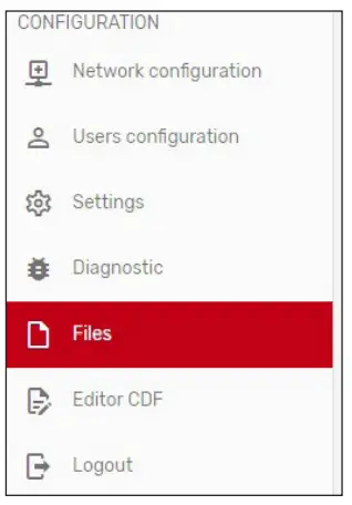
- Here you should click the “Upload” button and click on your logo customization PNG file.

- Refresh the page to see your changes.
Color Customization
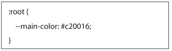
- You can also customize colors by creating a custom_style.css. This is an example of a custom_ style.css
- Upload the file in the same way as specified above under the “Files” menu and click “Upload”.
- Refresh the page to see your changes.
Here is an example of customizing the main colour into blue.
Removing Customizations
- If you want to remove a customization, simply remove the file in the “Files” list using the icon:
 on the right.
 - Refresh the page to see your changes.
Use Cases
Use Case 1: Source BACNET & Destination MODBUS
- As a step 1, User must activate the “source of the data”. It could be BACNet IP or MSTP from the Client Fieldbus configuration page. Main parameters to set up are: G41 or G42.
- G55 parameter is use as write priority property for BACNet protocol: Default is 16.
- G43 parameter is used as max number of units: Default is 127.
- After this configuration done, X-Gate will start to automatically scan the network (IP or Serial as per configuration done) and automatically will create all the CDF files of the discovered devices (nodes) and create the related device in the Network Configuration page.
- User can modify the CDF file directly using the CDF Editor or use as it is.
- As a step 2, User must activate the “Destination of the data”, in this case Modbus TCP/IP.
- In the Server Fieldbus page, the main parameter is G01 and later the G48 as default port of the server at 502.
- With this configuration, X-Gate is reading BACNET and exposing over MODBUS TCP/IP.
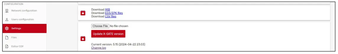
In case of sharing data with a local BMS, the full list of variable/data-points can be downloaded as a CVS file with the utility in settings download CSV file.

In case the destination of the data is the System Manager over Modbus RTU (serial RS485), G11 parameter must be on.
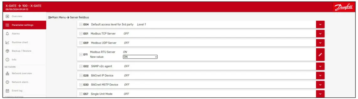
In this case, User must set up the communication port with the correct enabled feature. S10 parameter must have the correct set up “Modbus server” and the parameter SU2 and SU3 must be set up according.

Finally, User can download the file for the System Manager integration from the settings menu with the download of the ED3 / EPK files.
Use Case 2(1) Source CANBUS & Destination MODBUS
As a step 1, User must activate the “source of the data” with parameter G36.
(1) Feature available starting from software version greater than 5.22.
Create a new Device on the Network Configuration page.

- As a step 2, User must activate the “Destination of the data”, in this case Modbus TCP/IP.
- In this case, the activities to be done are the same already described for the Use-Case 01 to set up the destination of the data.
Use Case 3: Source MODBUS & Destination MODBUS
- As step 1, User must activate the “source of the data”. In this case X-Gate must have the additional expansion card with the extra RS485 port.
- G35 parameter to enable the use of the extra RS485.
- SU2 and SU3 for the serial line configuration of COM1
- SU5 and SU6 for the serial line configuration of COME (extended)
- S10 for COM1 as Client
- S40 for COME as Server
- Import the CDF file or create/modify an existing one with the CDF Editor (as done for Use Case 2).
- Create a new Device in the Network Configuration page (as done for Use Case 2).
- As a step 2, User must activate the “Destination of the data”, in this case Modbus TCP/IP. In this case the activities to be done are the same already described for the Use Case 1 to set up the destination of the data.
Use Case 4: Source XML Interface & Destination MODBUS
- As a step 1, User must activate the “source of the data” with parameter G31 to on.
- G32 parameter with the System Manager IP address (please consider also to add the port number like IP:PORT)
- G33 parameter with a valid User defined into System Manager
- G34 parameter with the password of the User

After this configuration done, X-Gate will start to automatically collect data from the System Manager and automatically will create all the CDF files of the discovered devices (nodes) and create the related device in the Network Configuration page. As a step 2, User must activate the “Destination of the data”, in this case Modbus TCP/IP. In this case the activities to be done are the same already described for the Use Case 1 to set up the destination of the data.
Update
10.1 X-Gate Software
User can update the X-Gate software using the feature available in the settings page. Software can be downloaded from the official Danfoss “Software ADAP-KOOL” website. The final “*.bin” file must be imported and used for the upgrade.

CDF Files
User can upload / delete available CDF files on the X-Gate using the Files menu.

Annexure
Supported BACNET features
- Who Is Router to Network
- I Am Router to Network
- Reject Message to Network
- Router Busy to Network
- Router Available to Network
- What Is Network Number
- Network Number Is
- Confirmed Request
- Unconfirmed Request
- Simple ACK
- Complex ACK
- Error PDU
- Reject PDU
- Abort PDU
- Read Property
- Write Property
- Read Property Multiple
- Write Property Multiple
- Subscribe COV
- COV Notification
- Who Is
- I Am
- Who Has
- I Have
- Time Synchronization
- Device Communication Control
- BACnet objects:
- Device (D)
- Integer Value (IV)
- Positive Integer Value (PI)
- Analog Value (AV)
- Analog Output (AO)
- Analog Input (AI)
- Large Analog Value
- Binary Input (BI)
- Binary Output (BO)
- Binary Value (BV)
- Multistate Input
- Multistate Output
- Multistate Value
- Bitstring Value
- Character String Value
Supported BACNET properties
- Object Identifier
- Object Type
- Object Name
- Description
- Present Value
- Event State
- Units
- Resolution
- Out of service
- Status Flags
- Reliability
- Min Pres Value
- Max Pres Value
- Polarity
The X-Gate supports BACnet segmentation.
Danfoss A/S
- Climate Solutions
- danfoss.com
- +45 7488 2222
Catingues descriptions. d/Vertisementse. and whether male available in writ, orally, etectronically onice desian, wend, smal be considered informative, anchis only binding ifand to thuals, extent, explicit reference is made in a quotation or order confirmation. Danfoss cannot accept any responsibility for possible errors in catalogues, brochures, videos and other material. Danfoss reserves the right to alter its products without notice. This also applies to products ordered but not delivered provided that such alterations can be made without changes to form, fit or function of the product.
All trademarks in this material are property of Danfoss A/S or Danfoss group companies. Danfoss and the Danfoss logo are trademarks of Danfoss A/S. All rights reserved.
- © Danfoss | Climate Solutions | 2024.11
- BC491019063010en-000301 | 20
Documents / Resources
 |
Danfoss X-Gate Gateway Unit Type [pdf] User Guide X-Gate Gateway Unit Type, X-Gate, Gateway Unit Type, Unit Type, Type |


