
OPX21 Wireless Control Panel
User Manual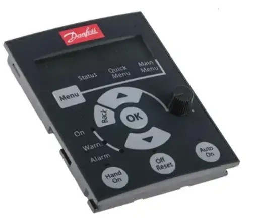
User Manual
Danfoss Wireless Control Panel OPXxx (DRAFT)
Danfoss A/S Ulsnaes 1 DK-6300 Graasten vlt-drives.danfoss.com
Classified as Business
Version log:
| Version | Initials | Date | Comments |
| 0.0 | EGK | 08.12.2021 | Document started |
The Wireless Control Panel
The main functionality of the wireless CP is to set up and control a drive manually via the build-in menu or/and act as a wireless gateway for this purpose (the wireless option is needed).
The application MyDrive® Insight can be installed on mobile, tablets, etc. devices. Download MyDrive® Insight from Google Play, Apple Store or go to Danfoss Drives App Suite.
Control Panel 2.8W OPX25: with display, NFC, and wireless;….136b7732
Control Panel 2.8 OPX21: with display and NFC; without wireless;….136b7731
Wireless Panel OPX01: without display; with NFC and wireless;…136b7733
Installation Instructions
2.1 Safety and Installation Awareness
Before starting the installation, familiarize yourself with the safety guidelines and precautions in the Safety Guide. For additional information about the control panel, consult Application Guides in the iC7 Series.
2.2 Verifying Shipment and Contents
2.2.1 Items Supplied
Make sure that the items supplied consist of any of the following control panel options.
 2.2.2 Control Panel Compatibility
All iC7 hardware products are compatible with the control panel options either mounted into the cradle in the iC7 drive, or front mounted and connected by a cable. For installation instructions on control panel mounting kits, see iC7 Series Control Panel Mounting Kits.
2.3 Installing the Control Panel
Procedure to attach control panel:
1. See illustration 1.11.3 in 2.6.1 Illustrations
Result
- The clip makes a click sound when properly aligned. The control panel is now locked into the cradle.
- A splash screen is shown during the power-up of the control panel. Check the status indicator lights on the control panel. Refer to 1.4 Status Indicators.
- After the control panel is powered on, the Home screen is shown. If security is enabled, the control panel display navigates to an Authentication screen.
2. To use MyDrive® Insight, install and launch MyDrive® Suite from Google Play, Apple Store or go to Danfoss Drives App Suite. Skip the step, if MyDrive® Suite is already installed.
3. Open MyDrive® Suite and install MyDrive® Insight.
Procedure to detach control panel:
1. See illustration 2.12.3 in 2.6.1 Illustrations
2.4 Status Indicators
The status of the drive is represented via the Halo and text LED indicators. The Halo and text LED indicators are available on all control panel options. The text LED indicators are Warn, Ready, and Fault.
Status indicators:
| Status | Halo and text LED Indicators In control panel options | |
| Status In Display | Status Description | Control Panel Options |
| Power On Not Ready | The drive Is powered on and not ready for operation. | Blinking White (1 Hz) |
| Ready for operation | The drive Is ready for operation. | On White |
| Fault | The drive has encountered fault(s). | On Red |
| Warning | The drive has encountered warnings. | On Yellow |
2.5 Installation instruction for best radio reception
This gives “Best Praxis” hints for setting up a drive with a wireless Control Panel or the remote placement of a wireless Control Panel.
2.5.1 Wireless CP installed in a drive

The best location for a drive with a wireless ICP:
- In general, it is good praxis to keep the drive clear from the ground/floor
- Keep it as clear as possible from other objects, particularly the font side
- Do not place obstacles in front of the drive
- If the drive has to be placed inside a cabinet use an extension cable to get the wireless ICP outside the cabinet
- Avoid places near other radiating devices e.g., router, transmitter, …
2.5.2 Wireless CP installed remotely in a cradle Best praxis for a remotely placed wireless control panel in a cradle:
- It is good praxis to place the cradle clear from the ground/floor in a vertical position
- Use only original Danfoss extension cables
- Keep it as clear as possible from other objects
- Keep a minimum clearance of 10cm from other cables behind the wireless control panel
- Do not place obstacles in front of the wireless control panel
- Avoid places near other radiating devices e.g., router, transmitter, …
2.6 Installation Illustrations
2.6.1 Illustrations
 Connection Procedure
Default operation mode is Off but can be configured for Access Point Mode or Client Mode operation from parameter xx-xx-yy WiFi Operation Mode.
| xx-xx-yy | WiFi Operation Mode | Access_Point_Mode Client_Mode Off |
3.1 Access Point Mode
The wireless SSID is Danfoss following the serial number of the iC7 Product. For example, Danfoss-012345678900 is the default wireless SSID for a product with the serial number 012345678900. The serial number can be located on the product label or alternatively from parameter xx-xx-0x Serial Number. Default Password is Danfoss1234
| xx-xx-0x | AP Wireless SSID | Danfoss-012345678900 |
- Open the MyDrive Insight app and establish the Wi-Fi connection, see the table for descriptions of the white Wi-Fi LED.
- When prompted, change the default password due to security restrictions. The password must be at least 8 and maximum 48 characters.
If the password is not changed, it leaves only 10 minutes for connecting and performing operations. After this, the wireless connection closes.
Reset password
If a password is forgotten, it can be reset from MyDrive Insight through the NFC interface on the control- or wireless panel or through the Service Port.
3.2 Client mode
| xx-xx-1x | CM Wireless SSID | Danfoss-123456789 |
| xx-xx-1y | CM Password | 123456789 |
- Open the MyDrive Insight app and establish a connection either wired or wireless.
- Configure the Client Mode SSID and Password according to the access point · Configure Wi-Fi Operation Mode to Client Mode operation
3.3 LED pattern
3.3.1 Status indicators
Status | Panel options | |
| Status type | Control Panel 2.8W | Status type |
| Power On Not Ready | Blinking White (1Hz) | Power On Not Ready |
| Ready for operation | On White | Ready for operation |
| Fault | On Red | Fault |
| Warning | On Yellow | Warning |
| Winking from an external application | Blinking (Yellow/White/Red) | Winking from an external application |
3.3.2 Wireless indicators Access Point Mode
| Wi-Fi Status | Panel options | |
| Wi-Fi Status type | Control Panel 2.8W | Wi-Fi Status type |
| Wi-Fi not active | The LED indicator shows no color. White Halo on the control panel. | Wi-Fi not active |
| Wi-Fi is active (Devices are connected or not connected) | LED indicator shows white color. White Halo on control panel. | Wi-Fi is active (Devices are connected or not connected) |
3.3.3 Wireless indicators Client Mode
Wi-Fi Status | Panel options | |
| Wi-Fi Status type | Control Panel 2.8W | Wi-Fi Status type |
| Wi-Fi not active | The LED indicator shows no color. White-colored halo on the control panel. | Wi-Fi not active |
| Wi-Fi is active (Devices are not connected) | LED indicator shows white color. White-colored halo on the control panel. | Wi-Fi is active (Devices are not connected) |
| Wi-Fi is active (Devices are connected) | The LED indicator shows white color. White-colored halo on the control panel. | Wi-Fi is active (Devices are connected) |
Safe Control
The safe control configuration allows the product to decide the behavior in cases where connectivity is lost from MyDrive Insight to the product through the Wi-Fi interface. This is only applicable when the product is in running operation.
| xx-xx-2x | Wi-Fi Timeout Action | Do nothing (Product continues to run)Stop the motor (Generic term to be found because the product could be a grid converter or an Active Front End) |
Approvals and certifications
5.1 EU Declaration of Conformity
The Control Panels comply with the following directives:
2014/53/EU……………..Radio Equipment Directive
2011/65/EU…………………….. RoHS Directive: Restriction of the use of certain hazardous substances
The following standards were consulted to assess conformity:
EN 300 328 v2.2.2
EN 300 330 v2.1.1
EN 301 489-1: v2.2.3 -17: v3.2.4
EN 60529:1991+A1:2000+A2:2013
IEC 62368-1: 2018
The CE symbol confirms that this product conforms with the above-mentioned norms and regulations.
The complete DoC can be found on the Danfoss website: www.Danfoss.com.
5.2 FCC compliance notice
This equipment has been tested and found to comply with the limits for a Class B digital device, pursuant to Part 15 of the FCC Rules. These limits are designed to provide reasonable protection against harmful interference in a residential installation. This equipment generates, uses, and can radiate radio frequency energy and, if not installed and used in accordance with the instructions, may cause harmful interference to radio communications. However, there is no guarantee that interference will not occur in a particular installation. If this equipment does cause harmful interference to radio or television reception, which can be determined by turning the equipment off and on, the user is encouraged to try to correct the interference by 1 or more of the following measures:
- Reorient or relocate the receiving antenna.
- Increase the separation between the equipment and receiver.
- Connect the equipment into an outlet on a circuit different from that to which the receiver is connected.
- Consult the dealer or an experienced radio/television technician for help.
Modifications: Any modifications made to this device that are not approved by Danfoss may void the authority granted to the user by the FCC to operate this equipment.
5.3 RF Exposure compliance
FCC Radiation Exposure Statement: This device complies with FCC’s and IC’s RF radiation exposure limits set forth for an uncontrolled environment under the following conditions:
- This device should be installed and operated such that a minimum separation distance of 20 cm is always maintained between the radiator (antenna) & user’s/nearby person’s body.
- This transmitter must not be co-located or operating in conjunction with any other antenna or transmitter. 3. Changes or modifications not expressly approved by the party responsible for compliance could void the user´s authority to operate the equipment.
Technical specifications
| Wireless Standards: | WiFi: 802.11 b/g/n BT classic v4.2 BLE v4.2 |
| Frequency range: | 2.4…2.5 GHz |
| Output power: | WiFi < 20 dBm BT < 10 dBm |
| WiFi security: | WPA2 (Personal) |
| WiFi operating mode: | Access Point or Client |
| Operating temperature: | -10 °C to +45 °C (+14 °F to +113°F) |
| Operating humidity: | 5-90% RH, non-condensing |
| Ingress protection: | 1P20 (1P55 with gasket) |
| Electrical rating: | 12V +/- 2V, 140mA |
| ‘ Dimensions: | 122.5 x 77.1 x 15.5 mm (I*w*th) 4.8 x 3.0 x 0.6 in (1*w*th) |
| . Weight: | 112 g 3.91 oz |
| Firmware update: | MyDrive Insight VI or higher |
| NFC type: | Passive tag |
| ‘ NFC standard: | ISO/IEC 14443, part 2 and part 3 compliant |
| ‘ Frequency: | 13,56MHz |
…end
Documents / Resources
 | Danfoss OPX21 Wireless Control Panel [pdf] User Manual CPVIK, 2ANSE-CPVIK, 2ANSECPVIK, OPX21, Wireless Control Panel, OPX21 Wireless Control Panel, OPX01, OPX25 |


