Danfoss EKE 1B Electronic Superheat Controller

Technical Specifications
- Analog inputs:
- Voltage: Max. 15 V
- NTC: 2
- Auxiliary Supplies: 1
- Digital inputs:
- Voltage-free contacts: 2
- Digital output: Relay
- RS-485 RTU Communication: 1
General Features and Warnings
- Operating conditions CE: -20°C to 60°C, 90% RH non-condensing
- Storage conditions: -30°C to 80°C, 90% RH non-condensing
- Index of protection: IP 20 on the product and IP40 only on the front cover
- Suitable for use in a normal pollution environment
CE Compliance
This product is designed to comply with EU standards:
- Low voltage guideline: 2014/35/EU
- Electromagnetic compatibility EMC: 2014/30/EU
Product Warnings
DIN rail mounting/demounting: The unit can be mounted onto a 35 mm DIN rail simply by snapping it into place and securing it with a stopper to prevent sliding. It is demounted by gently pulling the stirrup located in the base of the housing.
Product Usage Instructions
Installation
- Ensure power is disconnected before installation.
- Mount the superheat controller securely on a DIN rail using the provided stopper.
- Connect analog and digital inputs as per specifications.
- Ensure proper grounding for reliable operation.
Configuration
- Refer to the user manual for detailed configuration steps.
- Set the appropriate voltage and current limits based on your system requirements.
- Calibrate the NTC inputs for accurate temperature readings.
Troubleshooting
- If experiencing communication issues, check RS-485 connections.
- Verify power supply and ensure proper voltage levels.
- Contact customer support for advanced troubleshooting steps.

Electronic superheat controller
Type EKE 1B (PV05)
Introduction
- Superheat controller EKE 1B is for use where superheat must be accurately controlled, typically in commercial air conditioning, Commercial and industrial heat pumps, Commercial refrigeration, food retailing and industrial applications.
- Compatible valves: Danfoss ETS 6 / ETS 8M (Bipolar) / ETS / ETS Colibri®, / ETS L, KVS / KVS Colibri® and CCM / CCMT / CCMT L / CTR valves.
- Reference: For details, please see the EKE data sheet.

Applications
Superheat controller: standalone / network

Valve driver

Dimensions in mm EKE 1B

Weight: 152 gram
TECHNICAL SPECIFICATIONS
POWER SUPPLY
- EKE has galvanic isolation by switch-mode power supply.
- 24 V AC ± 20 %, 50/60 Hz. Maximum power consumption: 18 VA. Input voltage rating (DC): 24 V DC ± 20%, 15 W.
| I/O | TYPE | NUMBER | SPECIFICATION |
|
Analog inputs | Max. 15 V input voltage Do not connect voltage sources to unpowered units without limiting the current to analog inputs (overall 80 mA). Open circuit HW diagnostics available for voltage input on : AI4 | ||
| Voltage | 2 | AI3 (Pe) 0 – 5 V ratiometric, AI4 0 – 5 V , 0 – 10 V | |
| NTC | 2 | AI1 (S3, S4), AI2 (S2) NTC temperature probes, 10 kO at 25 °C | |
| Auxiliary Supplies | 1 | 5 V + Sensor supply: 5 V DC / 15 mA, overload protection approximately 150 mA | |
| Digital inputs | Voltage free contacts |
2 | DI1, DI2 Steady current minimum 1mA Cleaning current 100 mA at 15 V DC On: RIL < = 300 O Off: RIH > = 3.5 k O |
| Digital output | Relay | 1 | C1-NO1 Normally Open: 3 A General purpose, 250 V AC, 100 k cycle Normally Open: 3 A Inductive (AC-15), 250 V AC, 100 k cycle Normally Closed: 2 A General purpose, 250 V AC, 100 k cycle |
|
Stepper motor |
Bipolar |
1 | Stepper valves: A1, A2, A3, A4 Bipolar stepper motor output: – Danfoss ETS 8M (Bipolar) / ETS C / ETS L / KVS / KVS C / CCMT 2 – CCMT 42, CCMT L / CTR Valves Other Valves: – speed 10 – 400 pps – drive mode 1/8 microstep – max. peak phase current: 1.2 A (848 mA RMS) – max. drive voltage 40 V – max. output power 12 W |
| Battery backup | 1 | VBATT: 18 – 24 V DC (24 V DC recommended): – max. battery current: 850 mA at 18 V – battery alarm will be activated below 16 V DC and above 27 V DC | |
| Communication | RS-485 RTU | 1 | RS485 Galvanic isolation No Built-in termination |
| CAN | 1 | CAN – RJ RJ connector to directly connect and supply a MMI |
GENERAL FEATURES AND WARNINGS
PLASTIC HOUSING FEATURES
- DIN rail mounting complying with EN 50022
- Self-extinguishing V0 according to IEC 60695-11-10 and glowing/hot wire test at 960 °C according to IEC 60695-2-12
- Ball test: 125 °C according to IEC 60730-1. Leakage current: ≥ 250 V according to IEC 60112
OTHER FEATURES
- Operating conditions CE: -20T60, 90% RH non-condensing
- Storage conditions: -30T80, 90% RH non-condensing
- To be integrated in Class I and/or II appliances
- Index of protection: IP 20 on product and IP40 only on the front cover
- Period of electric stress across insulating parts: long
- Suitable for using in a normal pollution environment
- Category of resistance to heat and fire: D
- Immunity against voltage surges: category II
- Software class and structure: class A
CE COMPLIANCE
This product is designed to comply with the following EU standards:
- Low voltage guideline: 2014/35/EU
- Electromagnetic compatibility EMC: 2014/30/EU and with the following norms:
- EN61000-6-1, EN61000-6-3 (immunity for residential, commercial and light-industrial environments)
- EN61000-6-2, EN61000-6-4 (immunity and emission standard for industrial environments)
- EN60730 (Automatic electrical controls for household and similar use)
GENERAL WARNINGS
- Every use that is not described in this manual is considered incorrect and is not authorized by the manufacturer
- Verify that the installation and operating conditions of the device respect those specified in the manual, especially concerning the supply voltage and environmental conditions
- This device contains live electrical components. All service and maintenance operations must therefore be performed by qualified personnel
- The device must not be used as a safety device
- Liability for injury or damage caused by the incorrect use of the device lies solely with the user
INSTALLATION WARNINGS
- Recommended mounting position: vertical
- Installation must comply with local standards and legislation
- This product is not subject to the UK PSTI regulation, as it is for supply to and use only by professionals with the necessary expertise and qualifications. Any misuse or improper handling may result in unintended consequences. By purchasing or using this product, you acknowledge and accept the professional-use-only nature of its application. Danfoss does not assume any liability for damages, injuries, or adverse consequences (“damage”) resulting from the incorrect or improper use of the product and you agree to indemnify Danfoss for any such damage resulting from your incorrect or improper use of the product.
- Before working on the electrical connections, disconnect the device from the main power supply
- Before carrying out any maintenance operations on the device, disconnect all electrical connections
- For safety reasons the appliance must be fitted inside an electrical panel with no live parts accessible
- Do not expose the device to continuous water sprays or to a relative humidity greater than 90%.
- Avoid exposure to corrosive or pollutant gases, natural elements, environments where explosives or mixes of flammable gases are present, dust, strong vibrations or shock, large and rapid fluctuations in ambient temperature that might cause condensation in combination with high humidity, strong magnetic and/or radio interference (e.g. transmitting antennae)
- When connecting loads be aware of the maximum current for each relay and connector
- Use cable ends suitable for the corresponding connectors. After tightening connector screws, tug the cables gently to check their tightness
- Use appropriate data communication cables. Refer to the EKE data sheet for the kind of cable to be used and setup recommendations
- Minimize the length of probe and digital input cables as much as possible, and avoid spiral routes around power devices. Separate from inductive loads and power cables to avoid possible electromagnetic noises
- Avoid touching or nearly touching the electronic components fitted on the board to avoid electrostatic discharges
PRODUCT WARNINGS
- Use a class II category transformer for 24 V AC power supply.
- Connecting any EKE inputs to mains voltage will permanently damage the controller.
- Battery Backup terminals does not generate power to recharge a device connected.
- Battery backup – the voltage will close the stepper motor valves if the controller loses its supply voltage.
- Do not connect an external power supply to the digital input DI terminals to avoid damaging the controller.

DIN rail mounting/demounting
The unit can be mounted onto a 35 mm DIN rail simply by snapping it into place and securing it with a stopper to prevent sliding. It is demounted by gently pulling the stirrup located in the base of the housing.

Connection overview: EKE 1B

Connection overview, EKE 1B

Sensor mounting: Temperature sensor
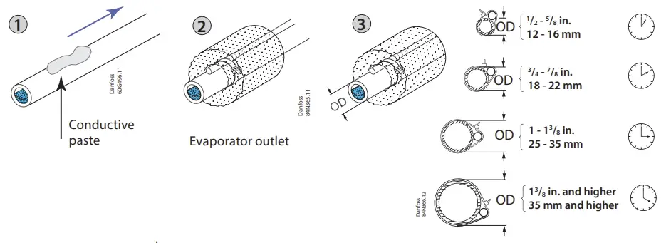
Important Note
- Mount the sensor on a clean paint-free surface.
- Remember to use heat-conducting paste and insulate the sensor.
- For precise measurements, mount the sensor max. 5 cm from the outlet of the evaporator.

Pressure transmitter
- Installation of the pressure transmitter is less critical. However, the pressure transmitter should be closer to the temperature sensor, right after the evaporator and with its head upright. It is a good practice to select a pressure transmitter with an average load of 40 – 60% of full scale.
- 5 EKEs at maximum are allowed to share the output signal of a ratiometric pressure transmitter.
- In order to get a correct acquisition on all the units all three wires (GND, 5 V and transmitter signal output) must be routed to every unit.
Power supply
- Power sharing is allowed in EKE controller.
- It is a good practice not to reverse the polarity of the power connection cables.
- Selection of the common power supply depends on the total number of sharings and the valve in use.

Relay Outputs
EKE 1B has 1 relay output:
- Type SPDT relay. Digital Output can be used to connect either a solenoid valve or an alarm.
- The relays cannot be used for the direct connection of capacitive loads such as LEDs and ON/OFF control of EC motors. All loads with a switch-mode power supply must be connected with a suitable contactor or similar.
Cable length
EKE controller supports the following max. cable length.
| Cable length | Wire size min. / max. | |
| [m] | [m2] | |
| Analog inputs (Current/Voltage) | max. 10 | 0.14 / 1.5 |
| Temperature sensor | max. 10 *) | – |
| Stepper valve connection | max. 30 | 0.14 / 1.5 |
| Power supply | max. 5 | 0.2 / 2.5 |
| Digital input | max. 10 | 0.14 / 1.5 |
| Digital output | – | 0.2 / 2.5 |
| Digital MMI | max. 3 over CAN RJ | – |
| Communication bus | max. 1000 | 0.14 / 1.5 |
Cable and wiring
- The max. cable distance between the controller and the valve depends on many factors like shielded/unshielded cable, the wire size used in the cable, the output power for the controller and EMC.
- Keep controller and sensor wiring well separated from mains wiring.
- Connecting sensors by wires more than the specified length may decrease the accuracy of measured values.
Warning
Separate the sensor and digital input cables as much as possible (at least 10 cm) from the power cables to the loads to avoid possible electromagnetic disturbance. Never lay power cables and probe cables in the same conduits (including those in the electrical panels).
Connecting Modbus
- For the MODbus cable, it is best to use 24 AWG shielded twisted-pair cable with a shunt capacitance of 16 pF/ft and 100Ω impedance.
- The controller provides an insulated RS-485 communication interface, which is connected to the RS-485 terminals (see connection overview).
- The max. permissible number of devices simultaneously connected to RS485 cable output is 32. The RS485 cable is of impedance 120 Ω with maximum length of 1000 m.
- Terminal resistors 120 Ω for terminal devices are recommended at both ends.
- The EKE communication frequency (baud rate) can be one of the following: 9600, 19200 or 38400 baud, default 19200 8 E 1.
- The default unit address is 1, which can be changed using the parameter “G001 Controller adr.”.
 For a detailed explanation of Modbus installation and setting software parameters, see:
- Data sheet for “EKE Superheat controller” and “EKD EIM Data Communication Modbus RS485 RTU”.
Stepper Motor Output
- All valves are driven in a bipolar mode with a 24 V supply chopped to control the current (Current driver).
- The stepper motor is connected to the “Stepper Valve” terminals (see terminal assignment) with a standard M12 connection cable.
- To configure stepper motor valves other than Danfoss stepper motor valves, the correct valve parameters must be set as described in the Valve configuration section (see manual for details).
- The default valve setting in EKE 1B is: none.
- The correct valve must be defined in “Valve configuration”, i.e. parameter I067. An overview of valve types is given in the “Parameter identification” section.
Valve Cable Connection
| Stepper valve connector | ETS/KVS/CCM/ CCMT/CTR/ CCMT L (Using Danfoss M12 Cable) | ETS 8M Bipolar | ETS 6 |
| A1 | White | Orange | Orange |
| A2 | Black | Yellow | Yellow |
| B1 | Red | Red | Red |
| B2 | Green | Black | Black |
| Not connected | – | – | Grey |
- All valves are driven in a bipolar mode with a 24 V supply chopped to control the current (Current driver).
- The stepper motor is connected to the “Stepper Valve” terminals (see terminal assignment) with a standard M12 connection cable.
- To configure stepper motor valves other than Danfoss stepper motor valves, the correct valve parameters must be set as described in the Valve configuration section by selecting user defined valve.
Guideline for long M12 cables on Danfoss stepper motor valves
- Long cables will lead to degradation of performance.
- You can overcome this degradation by changing the settings for the valve driver. This guideline is based on the cable type being the same type as the standard Danfoss stepper motor cable.
Recommended wire size and cable distance between EKE controller and stepper motor valve
| Recommended wire size and cable distance between EKE controller and stepper motor valve | ||
| Cable length | 1 m – 15 m | 15 m – 30 m |
| Wire diameter | 0.52 / 0.33 mm2 (20 / 22 AWG) | 0.33 mm2 (20 AWG) |
LED indication

(A) Two status LEDs to indicate operational status
- Steady green = power ON
- Flashing green = data transmission/initialization
- Flashing red = alarm/error condition
(B) Two status LEDs to indicate valve operation
- Flashing red = valve closing
- Steady red = valve fully closed
- Flashing green = valve opening
- Steady green = valve fully open
- Both green and red flashing = valve-related alarm
USER INTERFACE
EKE 1B can be setup using one of the following user interfaces:
- Danfoss KoolProg software
- Danfoss MMIGRS2 external display
- Communication bus: Modbus RS485 RTU
KoolProg
- KoolProg is a software tool for quickly and easily configuring EKE controllers. It enables you to make online changes to parameter configuration, copy settings to multiple controllers, monitor the live status of input/outputs, and quickly analyze controller behavior and program patterns with a graphical trending tool.
- KoolProg Software is available for download free of charge at http://koolprog.danfoss.com.
- KoolProg requires a Gateway (code 080G9711) to connect to the PC.
- Always use the latest KoolProg version and the User must check the software version of EKE and create a configuration file in KoolProg for that version. Configuration made with the different software version should not be copied to controller.

 Important note!
To guarantee a reliable USB connection to a host device (e.g. industrial PC), you must:
- Connect terminals R and H on the MMIMYK CAN port using a termination wire.
- Place cable holder close to MMIMYK to keep USB connector firmly in place.
- Keep USB cable length < 1 m.
- Place MMIMYK and route USB cable far from noise sources (inverter, motors, contactors etc.)
Danfoss MMIGRS2 display
- Connecting external MMIGRS2 display
- MMIGRS2 display can be used to set up EKE 1B. The display can be used not only for setting up the necessary parameters, but also as an external display during operation to show important parameters, e.g. degree of opening of valve, superheat, etc.

Important note:
- Max. distance between controller and display is 3 m over CAN RJ.
- CANbus requires termination in both ends of the cable by a 120 Ohm resistor to ensure reliable communication.
- External power for MMIGRS2 is not needed while using CAN RJ connector
MMIGRS2 (Back view)

MMIGRS2 (Front view) 
Note: Setup and service menu requires login with the default password 100 ( daily use), 200 (service use) or 300 (commissioning use). Long press Enter key to access login menu.
Setup wizard via MMIGRS2 display
- When all connections to the controller have been made, after the power is switched on, the Danfoss logo will appear for 5 seconds, then the Home screen will be displayed.
- To access the Wizard: press and hold enter to access the Login screen, the commissioning password is 300, scroll down the Setup and service menu and select “Setup wizard”.
- The Wizard workflow is: a. Language selection; b. Application selection; c. Input configuration, and d.
- Output configuration.
- When using the Setup Wizard, repeat the following sequence for all parameter settings:
- From Setup wizard, select the relevant parameters.
- Press ENTER to highlight 1st option
- Scroll with UP / DOWN to your desired option
- If the selected default value is acceptable, press DOWN to get to the next settings. Otherwise, press ENTER to set your choice
- Scroll with DOWN to the next parameter (repeat sequence a. to e.)
Note:
- If you do not have sufficient information to complete the Wizard, leave settings on their default values. To generate the requested info, you can use Danfoss Coolselector2 software to calculate operating conditions and valve OD for the same operating point.
- Setup Wizard only covers the most important parameters. If other features are to be enabled (e.g. Alarm settings, MOP/LOP, etc.), they must be configured separately once the Setup Wizard is done.’
- Setup Wizard is also available in KoolProg PC tool.
- The workflow process is the same as that described above for MMIGRS2 display. For details, please refer to EKE data sheet.

Quick guide for parameter selection
Apart from wizard setup, users can also use the following section which describes quick parameter settings for general applications.

EKE 1B – Commonly used parameter identification
- PNU – equivalent to the Modbus register no. (Modbus address +1).
- Actual value are read/written as 16-bit integer values without decimals. This is the default value as read via Modbus.
| Parameter | PNU | Default | Description | |||||||||||||||||||||||||||||||||||||||||||||||||||||||
| R012 Main switch | 3001 | 0 | 0 = regulation Off | 1 = regulation On | |||||||||||||||||||||||||||||||||||||||||||||||||||||||
| R102 Operation mode | 3002 | 0 | 0 = Superheat control | 1 = Valve driver | |||||||||||||||||||||||||||||||||||||||||||||||||||||||
| O002 Dl1 configuration | 3101 | 1 | 0 = Bus->Start/Stop | 1 = Main Switch | |||||||||||||||||||||||||||||||||||||||||||||||||||||||
| I091 Driver reference configuration | 3282 | 0 | 0 = Voltage to OD | 1 = Modbus to OD | 2 = Modbus to steps | |||||||||||||||||||||||||||||||||||||||||||||||||||||||
| I034 Ext ref. voltage low | 3130 | 0 | Range 0 – 10 V. To be used with l091 | |||||||||||||||||||||||||||||||||||||||||||||||||||||||
| I035 Ext ref. voltage high | 3129 | 10 | Range 0 – 10 V. To be used with l091 | |||||||||||||||||||||||||||||||||||||||||||||||||||||||
|
I067 Valve configuration |
3132 |
0 | 0 = no valve, 1 = UserDef 2 = ETS 12C, 3 = ETS 24C, 4 = ETS 25C, 5 = ETS 50C, 6 = ETC 100C 7 = ETS 6, 8 = ETS 12.5, 9 = ETS 25, 10 = ETS 50, 11 = ETS 100, 12 = ETS 250, 13 = ETS 400 14 = KVS 2C, 15 = KVS 3C, 16 = KVS 5C 17 = KVS 15, 18 = KVS 42 19 = CCMT 0, 20 = CCMT 1 21 = CCMT 2, 22 = CCMT 4, 23 = CCMT 8, 24 = CCMT 16, 25 = CCMT 24, 26 = CCMT 30, 27 = CCMT 42 28 = CCM 10, 29 = CCM 20, 30 = CCM 30, 31 = CCM 40 32 = CTR 20 , 33 = CCMT 3L, 34 = CCMT 5L, 35 = CCMT 8L, 36 = CCMT 10L, 37 = ETS 175L, 38 = ETS 175L OFHT, 39 = ETS 250L, 40 = ETS 250L OFHT, 41 = ETS 400L, 42 = ETS 400L OFHT, 43 = ETS 500L, 44 = ETS 500L OFHT, 45 = ETS 8M Bipolar | |||||||||||||||||||||||||||||||||||||||||||||||||||||||
|
O030 Refrigerant |
3017 |
0 |
| |||||||||||||||||||||||||||||||||||||||||||||||||||||||
| I081 S2 sensor configuration | 3266 | 0 | 0 = Not defined | 1 = EKS 221 | 2 = ACCPBT NTC10K | 3 = MBT 153 10K | 4 = 112CP | 5 = Bus Shared | |||||||||||||||||||||||||||||||||||||||||||||||||||||||
| I083 S3 sensor configuration | 3264 | 0 | 0 = Not defined | 1 = EKS 221 | 2 = ACCPBT NTC10K | 3 = MBT 153 10K | 4 = 112CP | 5 = Bus Shared | |||||||||||||||||||||||||||||||||||||||||||||||||||||||
| I084 S4 sensor configuration | 3262 | 0 | 0 = Not defined | 1 = EKS 221 | 2 = ACCPBT NTC10K | 3 = MBT 153 10K | 4 = 112CP | 5 = Bus Shared | |||||||||||||||||||||||||||||||||||||||||||||||||||||||
| I085 Pe transmitter configuration | 3270 | 0 | 0 = Not defined | 1 = AKS 32R | 2 = ACCPBP Ratio | 3 = 112CP | 4 = OEM Ratio| 5 = NSK | 6 = AKS 32 1-5V | 7 = OEM Voltage | 8 = Bus shared | 9 =DST P110 | |||||||||||||||||||||||||||||||||||||||||||||||||||||||
| O020 Pe transmitter min. (in bar g) | 3115 | -1 | Define pressure range in bar gauge | |||||||||||||||||||||||||||||||||||||||||||||||||||||||
| O021 Pe transmitter max. (in bar g) | 3116 | 12 | Define pressure range in bar gauge |
| N021 SH reference mode | 3027 | 2 | 0 = Fixed SH | 1 = Loadap | 2 = MSS | 3 = Delta temp |
| N107 SH fixed setpoint ( K) | 3028 | 7 | Range 2 – 40 K |
| N009 SH max. ( K) | 3029 | 9 | Range 4 – 40 K |
| N010 SH min. ( K) | 3030 | 4 | Range 2 – 9 K |
| N116 SH ref. delta temp. factor ( %) | 3035 | 65 | Range 20 – 100 |
For a detailed parameter list and explanation, please check the EKE data sheet.
Related products
| MMIGRS2 Display | Power Supply | MMIMYK Gateway |
 |
|
|
| User interface module MMIGRS2 Display | AK-PS Input: 100 – 240 V AC, 45 – 65 Hz Output: 24 V DC: available with 18 VA, 36 VA and 60 VA | MMIMYK device is used as a gateway to connect EKEs and the PC tool i.e KoolProg software for parameter setting or data logging. |
| ACCTRD Input: 230 V AC, 50 – 60 Hz Output: 24 V AC, available with 12 VA, 22 VA and 35 VA | ||
| Pressure Transducer | Temperature Sensor | |
 |  | |
| AKS Pressure Tranducer Available with ratiometric and 4 – 20 mA. | PT 1000 AKS is a High precision temp. sensor AKS 11 (preferred), AKS 12, AKS 21 ACCPBT PT1000
NTC sensors EKS 221 ( NTC-10 Kohm) MBT 153 ACCPBT NTC Temp probe (IP 67 /68) | |
| NSK Ratiometric pressure probe | ||
| XSK Pressure probe 4 – 20 mA | ||
| ACCCBI Cable | Stepper motor valves | M12 cable |
 |  |
|
| ACCCBI cables for MMI display and gateway. | EKE is compatible with Danfoss stepper motor valves i.e Danfoss ETS 6, ETS, KVS, ETS Colibri®, KVS colibri®, CTR, CCMT | M12 Angle cable to connect Danfoss stepper motor valve and EKE controller |


- Any information, including, but not limited to information on selection of product, its application or use, product design, weight, dimensions, capacity or any other technical data in product manuals, catalogues descriptions, advertisements, etc. and whether made available in writing, orally, electronically, online or via download, shall be considered informative, and is only binding if and to the extent, explicit reference is made in a quotation or order confirmation. Danfoss cannot accept any responsibility for possible errors in catalogues, brochures, videos and other material.
- Danfoss reserves the right to alter its products without notice. This also applies to products ordered but not delivered provided that such alterations can be made without changes to form, fit or function of the product.
- All trademarks in this material are property of Danfoss AIS or Danfoss group companies. Danfoss and the Danfoss logo are trademarks of Danfoss A/S. All rights reserved.
FAQs
Q: What should I do if the relay output is not functioning?
A: Check the wiring connections and ensure the load does not exceed the relay specifications.
Q: How do I reset the controller to factory settings?
A: Refer to the user manual for specific instructions on resetting the controller.
Q: Can I connect multiple controllers in a network configuration?
A: Yes, the EKE 1B supports network communication for seamless integration of multiple controllers.
Documents / Resources
 | Danfoss EKE 1B Electronic Superheat Controller [pdf] Installation Guide EKE 1B, PV05, EKE 1B Electronic Superheat Controller, EKE 1B, Electronic Superheat Controller, Superheat Controller, Controller |