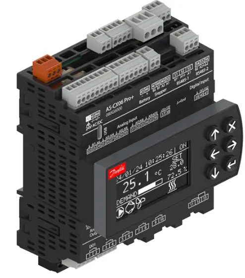
Danfoss AS-CX06 Programmable Controller
Specifications
- Model: Programmable controller Type AS-CX06
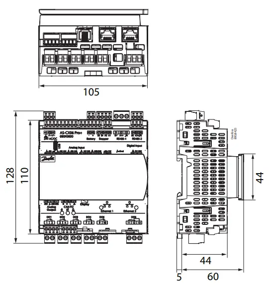
- Dimensions: 105mm x 44.5mm x 128mm (Without LCD display)
- Max. Nodes RS485: Up to 100
- Max. Baudrate RS485: 125 kbit/s
- Max. Nodes CAN FD: Up to 100
- Max. Baudrate CAN FD: 1 Mbit/s
- Wire Length RS485: Up to 1000m
- Wire Length CAN FD: Up to 1000m
Product Usage Instructions
System Connections
The AS-CX06 controller can be connected to various systems and devices, including:
- RS485 to BMS (BACnet, Modbus)
- USB-C for built-in Stepper Driver connections
- PC connection via Pen drive
- Direct Cloud connection
- Internal bus to I/O expansions
- Ethernet ports for various protocols including Web, BACnet, Modbus, MQTT, SNMP, etc.
- Connection to additional AS-CX controllers or Alsmart remote HMI
RS485 and CAN FD Communication
The RS485 and CAN FD ports are used for communication with fieldbus systems, BMS, and other devices. Key details include:
- RS485 bus topology should have line termination with external 120 Ohm resistors on both ends in a disturbed environment.
- Max. number of nodes for RS485: Up to 100
- CAN FD communication is used for device-to-device communication with similar topology requirements as RS485.
- Max. number of nodes for CAN FD: Up to 100
Input and Output Boards
The AS-CX06 features top and bottom boards for various inputs and outputs including analog and digital signals, Ethernet connections, battery back-up module inputs, and more.
Identification
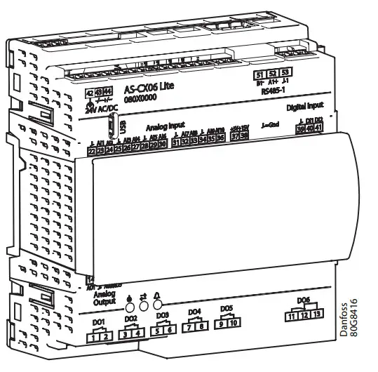
| AS-CX06 Lite | 080G6008 |
| AS-CX06 Mid | 080G6006 |
| AS-CX06 Mid+ | 080G6004 |
| AS-CX06 Pro | 080G6002 |
| AS-CX06 Pro+ | 080G6000 |
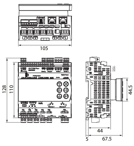
Dimensions
Without LCD display
With Snap-on LCD display: 080G6016
Connections
System connections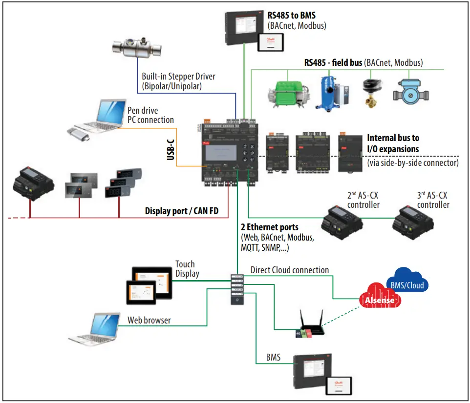 Top Board
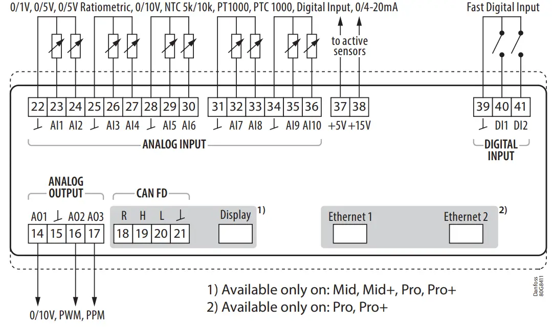 Bottom Board
input for battery back-up modules to secure closure of electronic stepper valves (e.g. EKE 2U)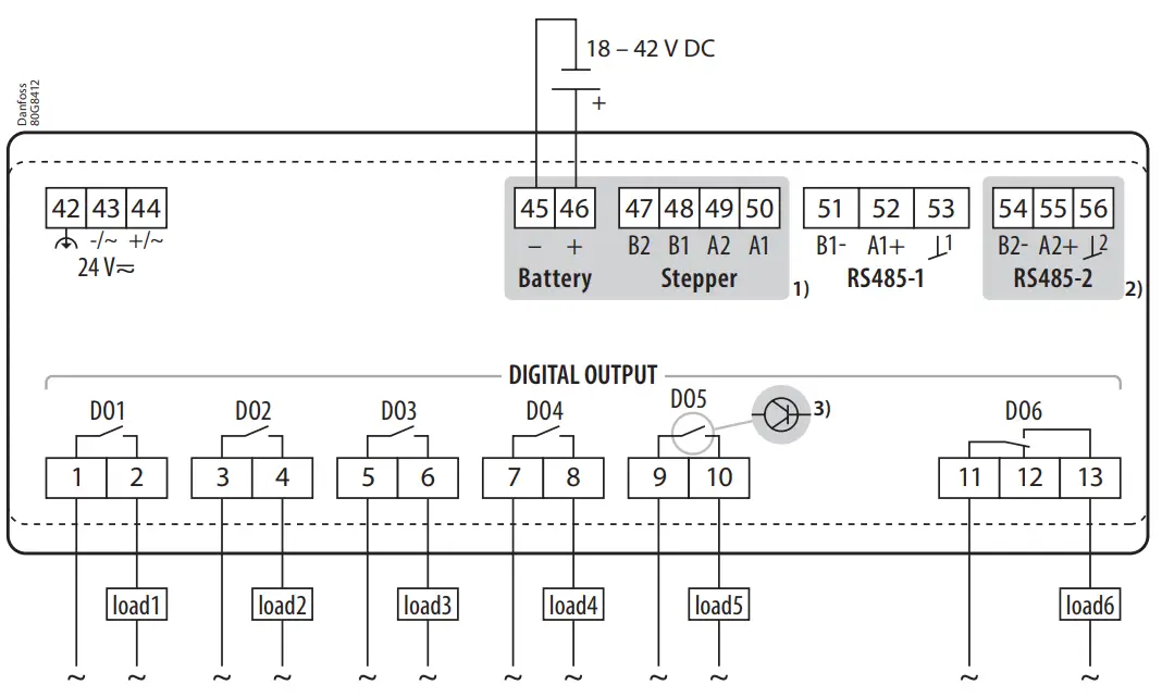
- Available only on: Mid+, Pro+
- Available only on: Mid, Mid+, Pro, Pro+
- SSR
 is used in the place of SPST relay on Mid+
Data communication
Ethernet (only for Pro and Pro+ versions)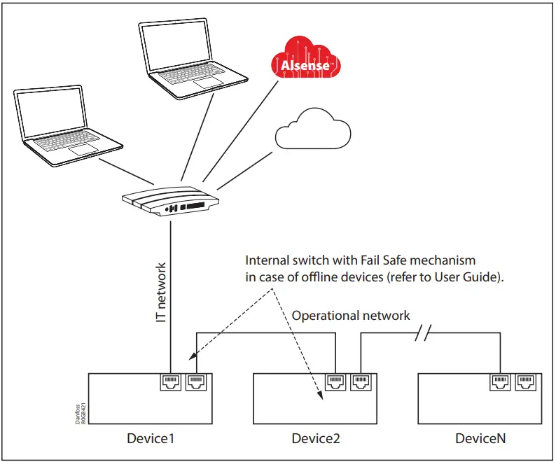 Point to point star topology with network hubs/switches. Each AS-CX device incorporates a switch with fail-safe technology.
- Ethernet type: 10/100TX auto MDI-X
- Cable type: CAT5 cable, 100 m max.
- Cable type connector: RJ45
First access information
The device automatically acquires its IP address from the network via DHCP.
To check the current IP address, press ENTER ![]() to access the default settings menu and select Ethernet Settings.
to access the default settings menu and select Ethernet Settings.
Enter the IP address in your preferred web browser to access the web front-end. You will be directed to a login screen with the following default credentials:
- Default User: Admin
- Default Password: Administrator
- Default Numeric Password: 12345 (to be used on LCD screen) You will be prompted to change your password after your initial successful login.
Note: there is not a way to retrieve a forgotten password.
RS485: Modbus, BACnet
RS485 ports are isolated and can be configured as client or server. They are used for fieldbus and BMS systems communication.
Bus topology Cable type recommendations:
- Twisted pair with ground: short leads (i.e. <10 m), no power lines in proximity (min. 10 cm).
- Twisted pair + ground and shield: long leads (i.e. >10 m), EMC- disturbed environment.
Max.. number of nodes: up to 100
| Wire length (m) | Max. baud rate | Min. wire size |
| 1000 | 125 kbit/s | 0.33 mm2 – 22 AWG |
CAN FD
CAN FD communication is used for device-to-device communication. It is also used to connect Alsmart remote HMI via display port.
Bus topology Cable type:
- Twisted pair with ground: short leads (i.e. <10 m), no power lines in proximity (min. 10 cm).
- Twisted pair + ground and shield: long leads (i.e. >10 m), EMCdisturbed environment
Max.. number of nodes: up to 100
| Wire length (m) 1000 | Max. baudrate CAN | Min. wire size |
| 1000 | 50 kbit/s | 0.83 mm2 – 18 AWG |
| 500 | 125 kbit/s | 0.33 mm2 – 22 AWG |
| 250 | 250 kbit/s | 0.21 mm2 – 24 AWG |
| 80 | 500 kbit/s | 0.13 mm2 – 26 AWG |
| 30 | 1 Mbit/s | 0.13 mm2 – 26 AWG |
Installation of RS485 and CAN FD
- Both fieldbuses are of two wire differential type, and it is fundamental for reliable communication to connect all the units in a network also with a ground wire.
Use one twisted pair of wires for connecting the differential signals and use another wire (for example a second twisted pair) for connecting the ground. For example:
- The line termination must be present on both bus ends to ensure proper communication.
The line termination can be installed in two different ways:- Make a short circuit on CAN-FD H and R terminals (only for CANbus);
- Connect a 120 Ω resistor between CAN-FD H and L terminals for the CANbus or A+ and B- for RS485.
- The installation of the data communication cable must be performed correctly with sufficient distance to high voltage cables.

- The devices should be connected according to the “BUS” topology. That means that the communication cable is wired from one device to the next without stubs.
If stubs are present in the network, they should be kept as short as possible (<0.3 m at 1 Mbit; <3 m at 50 kbit). Note that remote HMI connected to the display port makes a stub.
- There must be a clean (not disturbed) ground connection between all devices connected in the network. The units must have floating ground (not connected to earth), which is tied together between all units with the ground wire.
- In case of three three-conductor cable plus shield, the shield must be grounded in one location only.

Pressure transmitter info
Example: DST P110 with ratio-metric output ETS Stepper Valve info
 Valve cable connection
Maximum cable length: 30 m
CCM / CCMT / CTR / ETS Colibri® / KVS Colibri® / ETS / KVS
| Danfoss M12 cable | White | Black | Red | Green |
| CCM/ETS/KVS Pins | 3 | 4 | 1 | 2 |
| CCMT/CTR/ETS Colibri/KVS Colibri Pins | A1 | A2 | B1 | B2 |
| AS-CX terminals | A1 | A2 | B1 | B2 |
ETS 6
| Wire color | Orange | Yellow | Red | Black | Grey |
| AS-CX terminals | A1 | A2 | B1 | B2 | Not connected |
AKV info (only for Mid+ version) Technical data
Electrical specifications
| Electrical data | Value |
| Supply voltage AC/DC [V] | 24V AC/DC, 50/60 Hz (1)(2) |
| Power supply [W] | 22 W @ 24 V AC, min. 60 V A if transformer used or 30 W DC power supply(3) |
| Electrical cable dimensioning [mm2] | 0.2 – 2.5 mm2 for 5 mm pitch connectors 0.14 – 1.5 mm2 for 3.5 mm pitch connectors |
- 477 5×20 Series from LittelFuse (0477 3.15 MXP).
- A higher DC voltage can be applied if the control is installed in an application where the manufacturer declares a reference standard and a voltage level for accessible SELV/ PELV circuits to be considered non-hazardous by the application standard. That voltage level can be used as power supply input though 60 V DC must not be exceeded.
- US: Class 2 < 100 VA (3)
- In short circuit condition DC power supply must be capable of supply 6 A for 5 s or average output power < 15 W
Input/Output specifications
- Maximum cable length: 30m
- Analog input: AI1, AI2, AI3, AI4, AI5, AI6, AI7, AI8, AI9, AI10
| Type | Feature | Data |
| 0/4-20 mA | Accuracy | ± 0.5% FS |
| Resolution | 1 uA | |
| 0/5 V Radiometric | Relative to 5 V DC internal supply (10 – 90 %) | |
| Accuracy | ±0.4% FS | |
| Resolution | 1 mV | |
| 0 – 1 V 0 – 5 V 0 – 10 V | Accuracy | ±0.5% FS (FS intended specifically for each type) |
| Resolution | 1 mV | |
| Input resistance | >100 kOhm | |
| PT1000 | Meas. range | -60 to 180 °C |
| Accuracy | ±0.7 K [-20…+60 °C ], ±1 K otherwise | |
| Resolution | 0.1 K | |
| PTC1000 | Meas. range | -60…+80 °C |
| Accuracy | ±0.7 K [-20…+60 °C ], ±1 K otherwise | |
| Resolution | 0.1 K | |
| NTC10k | Meas. range | -50 to 200 °C |
| Accuracy | ± 1 K [-30…+200 °C] | |
| Resolution | 0.1 K | |
| NTC5k | Meas. range | -50 to 150 °C |
| Accuracy | ± 1 K [-35…+150 °C] | |
| Resolution | 0.1 K | |
| Digital Input | Stimulation | Voltage-free contact |
| Contact cleaning | 20 mA | |
| Other feature | Pulse counting function 150 ms denounce time |
Digital input: DI1, DI2
| Type | Feature | Data |
| Voltage free | Stimulation | Voltage-free contact |
| Contact cleaning | 20 mA | |
| Other feature | Pulse counting function max. 2 kHz |
Analog output: AO1, AO2, AO3
| Type | Feature | Data |
| Max. load | 15 mA | |
| 0 – 10 V | Accuracy | Source: 0.5% FS |
| Sink 0.5% FS for Vout > 0.5 V 2% FS whole range (I<=1mA) | ||
| Resolution | 0.1% FS | |
| Async PWM | Voltage output | Vout_Lo Max = 0.5 V Vout_Hi Min = 9 V |
| Frequency range | 15 Hz – 2 kHz | |
| Accuracy | 1% FS | |
| Resolution | 0.1% FS | |
| Sync PWM/ PPM | Voltage output | Vout_Lo Max = 0.4 V Vout_Hi Min = 9 V |
| Frequency | Mains frequency x 2 | |
| Resolution | 0.1% FS |
Digital output
| Type | Data |
| DO1, DO2, DO3, DO4, DO5 | |
| Relay | SPST 3 A Nominal, 250 V AC 10k cycles for resistive loads UL: FLA 2 A, LRA 12 A |
| DO5 for Mid+ | |
| Solid State Relay | SPST 230 V AC / 110 V AC /24 V AC max 0.5 A |
| DO6 | |
| Relay | SPDT 3 A Nominal, 250 V AC 10k cycles for resistive loads |
| Isolation between relay in the DO1-DO5 group is functional. Isolation between DO1-DO5 group and DO6 is reinforced. | |
| Stepper motor output (A1, A2, B1, B2) | |
| Bipolar/ Unipolar | Danfoss valves: • ETS / KVS / ETS C / KVS C / CCMT 2–CCMT 42 / CTR • ETS6 / CCMT 0 / CCMT 1 Other valves: • Speed 10 – 300 pps • Drive mode full step – 1/32 microstep • Max. peak phase current: 1 A • Output power: 10 W peak, 5 W average |
| Battery backup | V battery: 18 – 24 V DC(1), max. power 11 W, min. capacity 0.1 Wh |
Aux power output
| Type | Feature | Data |
| +5 V | +5 V DC | Sensor supply: 5 V DC / 80 mA |
| +15 V | +15 V DC | Sensor supply: 15 V DC / 120 mA |
Function data
| Function data | Value |
| Display | LCD 128 x 64 pixel (080G6016) |
| LED | Green, Orange, Red LED controlled by software application. |
| External display connection | RJ12 |
| Data communication built-in | MODBUS, BACnet for fieldbus and communication to BMS systems. SMNP for communication to BMS systems. HTTP(S), MQTT(S) for communication to web browsers and cloud. |
| Clock accuracy | +/- 15 ppm @ 25 °C, 60 ppm @ (-20 to +85 °C) |
| Clock battery backup power reserve | 3 days @ 25 °C |
| USB-C | USB Version 1.1/2.0 high speed, DRP and DRD support. Max. current 150 mA For connection to pen drive and laptop (refer to User Guide). |
| Mounting | DIN rail, vertical position |
| Plastic housing | Self extinguishing V0 and glowing/hot wire test at 960 °C. Ball test: 125 °C Leakage current: ≥ 250 V according to IEC 60112 |
| Type of control | To be integrated in Class I and/or II appliances |
| Type of action | 1C; 1Y for version with SSR |
| Period of electric stress across insulating | Long |
| Pollution | Suitable for use in environments with degree of pollution 2 |
| Immunity against voltage surges | Category II |
| Software class and structure | class A |
Environmental condition
| Environmental condition | Value |
| Ambient temperature range, operating [°C] | -40 to +70 °C for Lite, Mid, Pro versions. -40 to +70 °C for Mid+, Pro+ versions without I/O expansions attached. -40 to +65 °C otherwise. |
| Ambient temperature range, transport [°C] | -40 to +80 °C |
| Enclosure rating IP | IP20 IP40 on the front when plate or display are mounted |
| Relative humidity range [%] | 5 – 90%, non-condensing |
| Max. installation height | 2000 m |
Electric noise
Cables for sensors, low voltage DI inputs and data communication must be kept separate from other electric cables:
- Use separate cable trays
- Keep a distance between cables of at least 10 cm
- Keep I/O cables as short as possible
Installation considerations
- The controller should only be installed, serviced and inspected by qualified personnel and in compliance with national and local regulations.
- Before servicing the equipment, the controller must be disconnected from the power mains by moving the system main switch to OFF.
- Using a supply voltage other than specified can seriously damage the system.
- All the safety extra low voltage connections (analogue and digital inputs, analogue outputs, serial bus connections, power supplies) must have proper insulation from the power mains.
- Avoid touching or nearly touching the electronic components mounted on the boards to avoid electrostatic discharges from the operator to the components, which may cause considerable damage.
- Do not press the screwdriver on the connectors with excessive force, to avoid damaging the controller.
- In order to ensure sufficient convection cooling we recommend not obstructing ventilation openings.
- Accidental damage, poor installation, or site conditions can give rise to malfunctions of the control system, and ultimately lead to a plant breakdown.
- Every possible safeguard is incorporated into our products to prevent this. However, a wrong installation could still present problems. Electronic controls are no substitute for normal, good engineering practice.
- During installation, ensure that proper method is made to prevent a wire to get loose and create a potential risk in regards to shock or fire.
- Danfoss will not be responsible for any goods, or plant components, damaged as a result of the above defects. It is the installer’s responsibility to check the installation thoroughly and to fit the necessary safety devices.
- Your local Danfoss agent will be pleased to assist with further advice.
Certificates, declarations, and approvals (in progress)
| Mark(4) | Country |
| CE | EU |
| cULus (only for AS-PS20) | NAM (US and Canada) |
| cURus | NAM (US and Canada) |
| RCM | Australia/New Zealand |
| EAC | Armenia, Kyrgyzstan, Kazakhstan |
| UA | Ukraine |
The list contains the main possible approvals for this product type. Individual code number may have some or all of these approvals, and certain local approvals may not appear on the list.
Some approvals may be still in progress and others may change over time. You can check the most current status at the links indicated below.
EU declaration of conformity can be found in the QR code.

Information about usage with flammable refrigerants and others can be found in the Manufacturer Declaration in the QR code.

Information about usage with flammable refrigerants and others can be found in Manufacturer Declaration in the QR code.
DanfossA/S
Climate Solutions • danfoss.com • +45 7488 2222
Any information, including, but not limited to information on selection of product, its application or use, product design, weight, dimensions, capacity or any other technical data in product manuals, catalogues descriptions, advertisements, etc. and whether made available in writing, orally, electronically, on line or via download, shall be considered informative, and is only binding if and to the extent, explicit reference is made in a quotation or order confirmation. Danfoss cannot accept any responsibility for possible errors in catalogues, brochures, videos and other material. Danfoss reserves the right to alter its products without notice. This also applies to products ordered but not
delivered provided that such alterations can be made without changes to form, it or function of the product.
All trademarks in this material are property of Danfoss A/5 or Danfoss group companies. Danfoss and the Danfoss logo are trademarks of Danfoss A/5. All rights reserved.
FAQ
Q: How can I access the web front-end of the AS-CX06?
A: Enter the IP address in your preferred web browser. The default credentials are: Default User: Admin, Default Password: Administrator, Default Numeric Password: 12345 (for LCD screen).
Q: What is the maximum wire length supported by the RS485 and CAN FD connections?
A: The RS485 and CAN FD connections support wire lengths of up to 1000m.
Q: Can the AS-CX06 controller be connected to multiple AS-CX controllers or external devices?
A: Yes, the AS-CX06 controller supports connections to multiple AS-CX controllers, external sensors, fieldbus systems, and more.
Documents / Resources
 | Danfoss AS-CX06 Programmable Controller [pdf] Installation Guide AS-CX06 Lite, AS-CX06 Mid, AS-CX06 Mid, AS-CX06 Pro, AS-CX06 Pro, AS-CX06 Programmable Controller, AS-CX06, Programmable Controller, Controller |