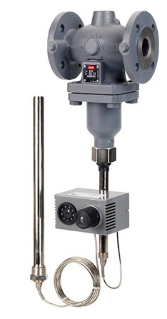
Danfoss AFT 06, 17 Actuator for Temperature Control
Safety Notes
Prior to assembly and commissioning to avoid injury of persons and damages of the devices, it is absolutely necessary to carefully read and observe these instructions. Necessary assembly, start-up, and maintenance work must be performed only by qualified, trained and authorized personnel.
Prior to assembly and maintenance work on the controller, the system must be:
- depressurized,
- cooled down,
- emptied and
- cleaned.
Please comply with the instructions of the system manufacturer or system operator. Disposal instruction
This product should be dismantled and its components sorted, if possible, in various groups before recycling or disposal.
- Always follow the local disposal regulations.
Definition of Application
The actuator AFT is used in combination with Danfoss valves for temperature control of water, water-glycol mixtures, and steam for heating, district heating, and cooling systems. The technical data on the rating plates determine the use.
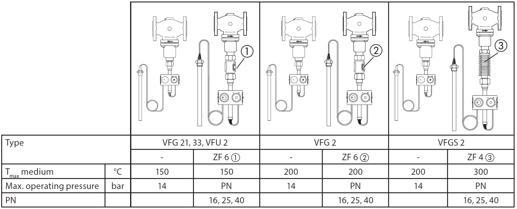
Permissible Pressures and Temperatures
Permissible Pressures and Temperatures ❶
Mounting
Mounting ❷
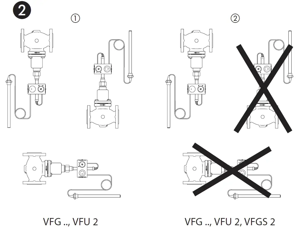
Permissible Installation Positions
- For valves VFG 2., VFG 3., VFU 2
- DN 15-80 medium temperatures up to120 °C
- For valves VFG 2., VFG 3., VFU 2
- DN 100-125 and for DN 15-80, medium temperature res > 120 °C and
- For valves VFGS 2
Installation Scheme
Valves VFG 2(1), VFGS 2, VFU ❸
Can be installed in the flow or the return pipe.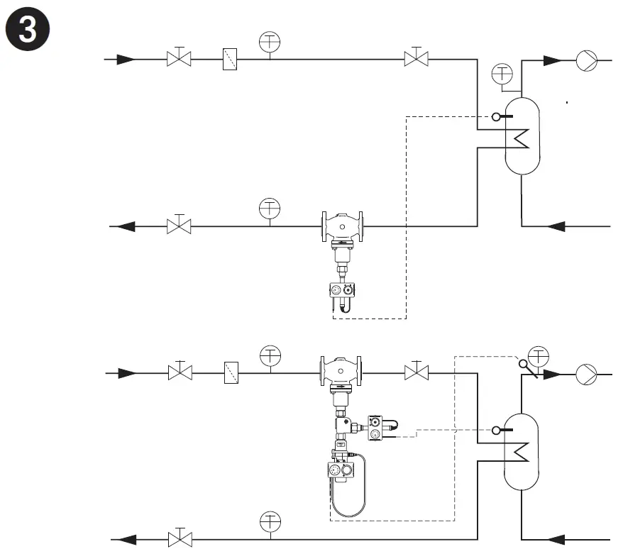
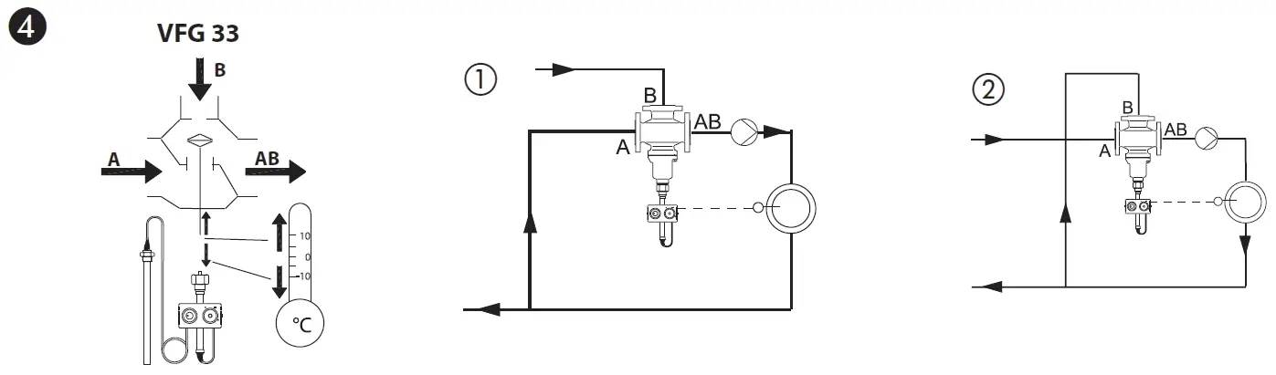
Mixing valve VFG 33 ❹
- Mixing valve in the supply flow heating
- Mixing valve in the supply flow cooling
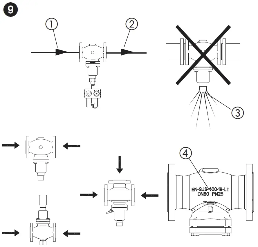
Valve Installation ❺
- Install a strainer in front of valve.
- Rinse system before installing valve.
- Observe flow direction ① on the valve body.
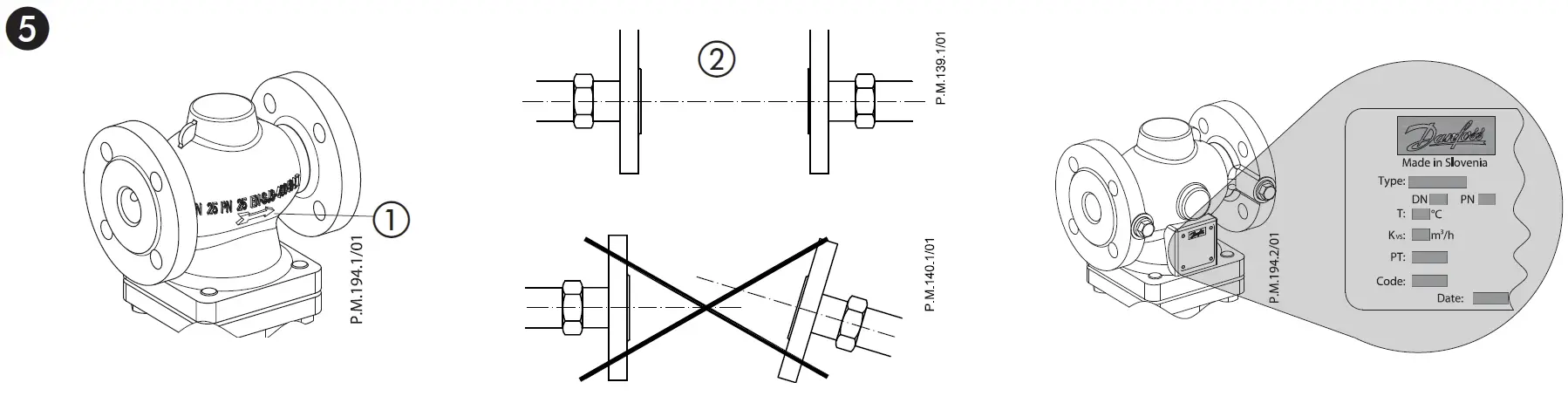
- Flanges ② in the pipeline system must be in parallel direction, the sealing surfaces must be clean and undamaged.
- Install valve.
- Tighten screws crosswise in 3 steps up to the maximum torque.
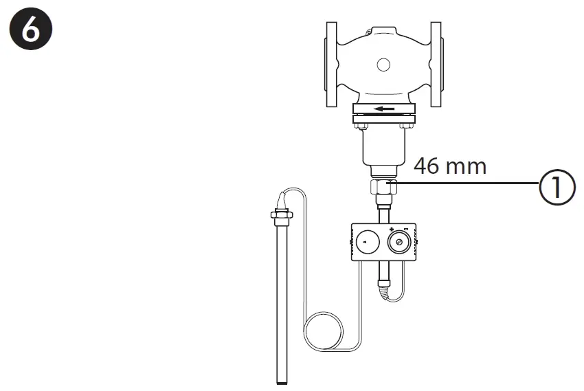
Actuator and Valve Mounting ❻
- Place actuator at the valve and align.
- Tighten union nut ①, torque 100 Nm
Temperature Sensor Installation ❼
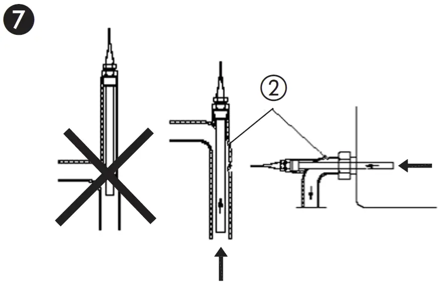
- The temperature sensor may be installed in any position
- The capillary tube may not be twisted or buckled. The minimum bending radius is 50 mm.
- The temperature of the medium has to be taken directly without any delay.
- Care for a sufficient cross-section of flow ②.
Filling the system and First Start-up ❽
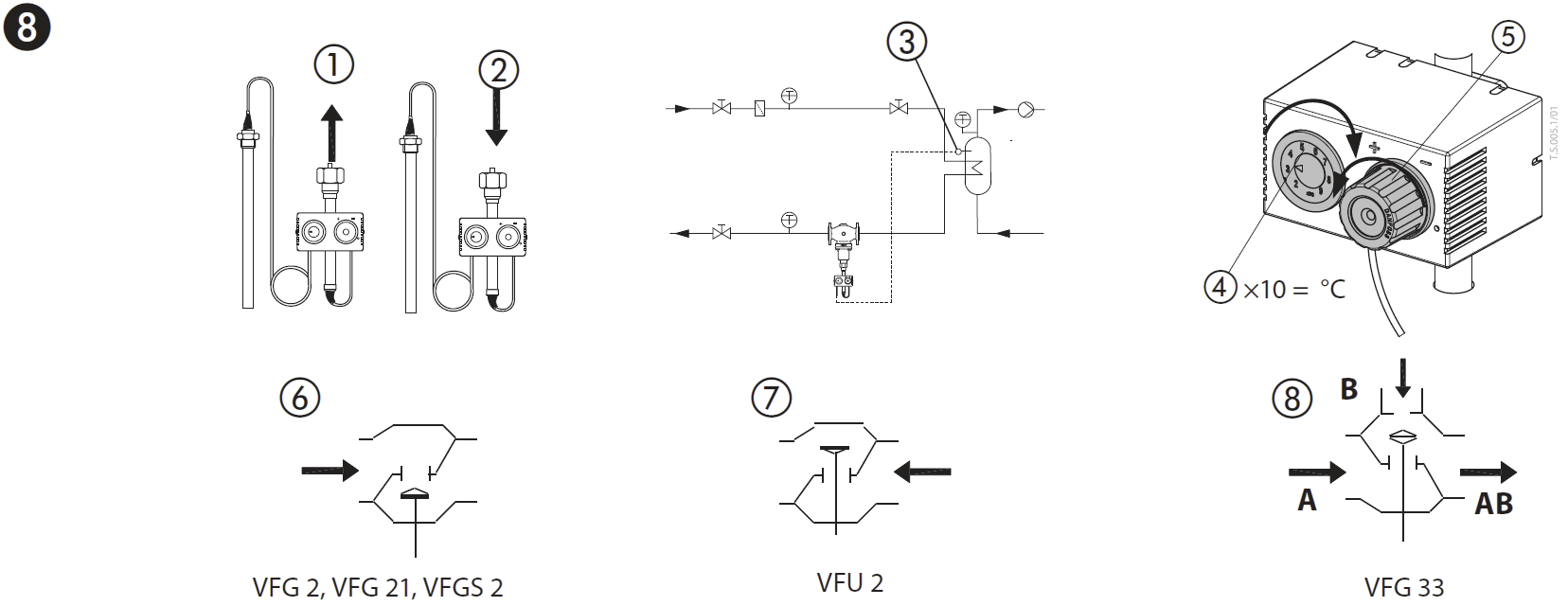
- When filling the system, the temperature control valve must be open. Alternatively, the filling can be carried out from all sides.
- To ensure that the temperature control valve is open, the following must be observed:
The stem of the actuator:
- is extended ①
- if the temperature at the sensor ③ is higher than the setpoint ④.
- is retracted ②
- if the temperature at the sensor ③ is lower than the setpoint ④.
- In order to open the temperature control valve, the setpoint at the setpoint adjuster ⑤ is to be increased or reduced, depending on the valve designs ⑥ – ⑧.
- The pressure ② behind the valve may exceed the pressure ① in front of the valve only insignificantly.
- Non-compliance may cause damages at the valve.
Pressure test
Pressure test ➒
- Carry out pressure tests only with the actuator mounted. Without actuator, the valve is open ③, the seal is in the actuator.
- It is absolutely necessary to constantly increase pressure from all sides. Non-compliance may cause damages at the controller.
- Observe nominal pressure ④ of the valve.
- Max. test pressure is 1.5 x PN
Setpoint Adjustment ❿
- Thermostats are proportional controllers, thus certain deviation from set point can be expected and varies from valve DN.
- The setpoint range is indicated on the rating plate.
- The system must be in operation. Set point need to be adjusted at 50% flow.
Adjustment
- Observe temperature indicator ①.
- Adjust setpoint by turning the setpoint adjuster (observe the scale for relevant valve VFG2/VFU2) ②.
- ③ increases the setpoint
- ④ reduces the setpoint
If the temperature at the sensor ① is noticeably higher than the setpoint temperature, then:
- return setpoint adjuster only in increments of max. 10 °C and
- wait until the temperature at the sensor dropped.
After having adjusted the setpoint, wait until the temperature indication ① shows its final value.
Scale on the setting knob is only the indication of the set temperature. The temperature setting need to be done based on the temperature reading from the thermometer.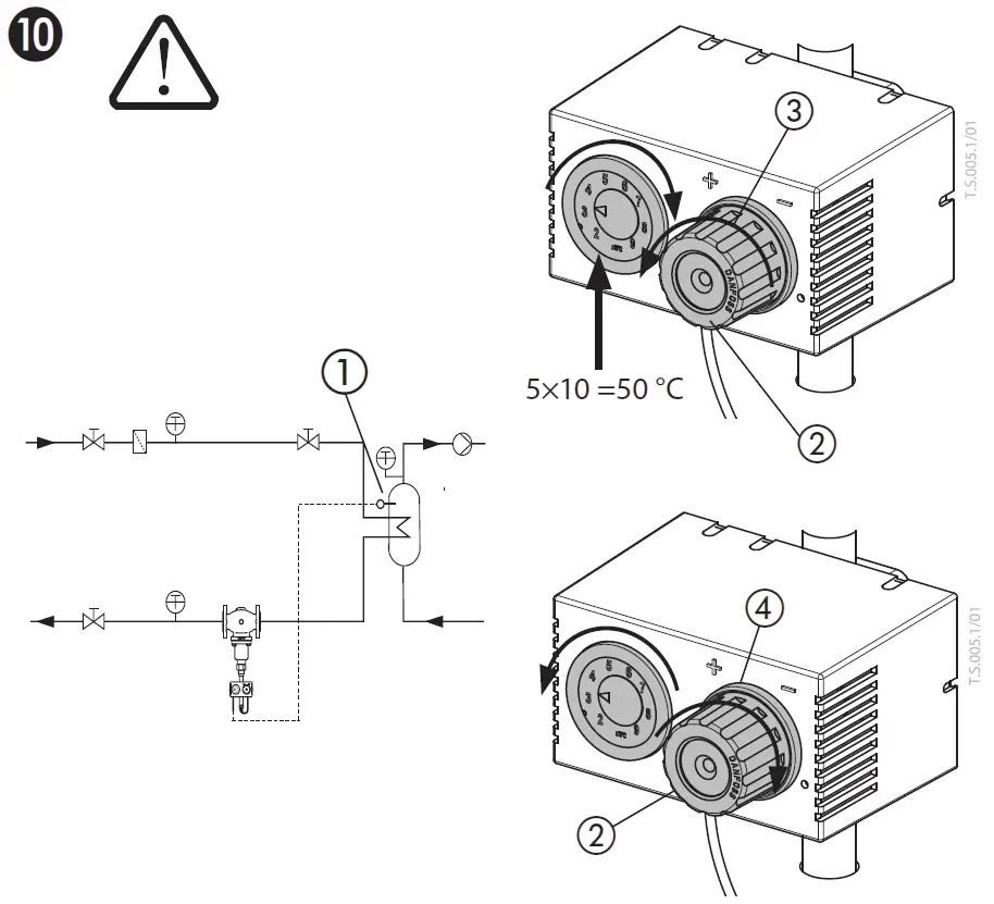
Dismounting of Valve and Actuator ⓫
Danger of injury by steam or hot water!.
Valve without actuator is open ①, sealing ② is in the actuator. It is absolutely necessary to depressurize system prior to dismounting.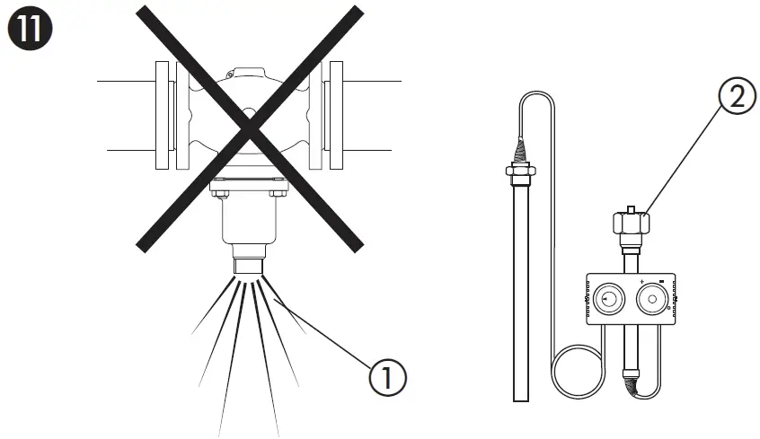
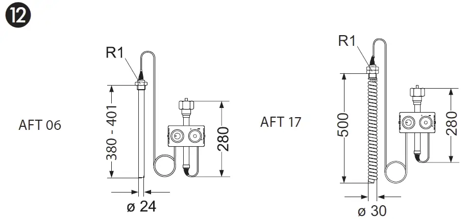
Dimensions
Dimensions ⓬
MORE INFORMATION
Danfoss can accept no responsibility for possible errors in catalogues, brochures and other printed material. Danfoss reserves the right to alter its products without notice. This also applies to products already on order provided that such alterations can be made without subsequent changes being necessary eady agreed. All trademarks in this material are the property of the respective companies. Danfoss and the Danfoss logotype are trademarks of Danfoss A/S. All rights reserved.
- Actuator for Temperature Control AFT 06, 17
FAQs
- Q: What should be done before assembly and maintenance work on the controller?
- A: Prior to any assembly or maintenance work, ensure that the system is depressurized, cooled down, emptied, and cleaned as per safety guidelines.
- Q: How should the product be disposed of?
- A: Disassemble the product and sort its components for recycling or disposal following local regulations.
- Q: What is the application of the actuator AFT?
- A: The actuator AFT is used with Danfoss valves for temperature control of water, water-glycol mixtures, and steam in heating, district heating, and cooling systems.
Documents / Resources
 | Danfoss AFT 06, 17 Actuator for Temperature Control [pdf] Instruction Manual AFT 06, AFT 17, VFG 2 1, VFGS2, VFU 2, VFG 33, AFT 06 17 Actuator for Temperature Control, AFT 06 17, Actuator for Temperature Control, Temperature Control, Control, Actuator |