
Indledning
Welcome to the ULTRICS Digital Multimeter D2 user manual. This device is designed for precise and reliable electrical measurements, suitable for professionals and DIY enthusiasts. It accurately measures AC/DC voltage, DC current, resistance, continuity, and diodes. This manual provides essential information for safe and effective operation, helping you to maximize the utility of your new multimeter.
Sikkerhedsoplysninger
ADVARSEL: Always exercise extreme caution when working with electrical circuits. Improper use of this multimeter can result in electric shock, personal injury, or damage to the device.
- Overskrid ikke de maksimale inputværdier for noget område.
- Do not use the multimeter if it or the test leads appear damaged. Inspect them before each use.
- Ensure the function switch is in the correct position before making measurements. Changing ranges while connected to a live circuit can cause damage.
- Disconnect power to the circuit before measuring resistance, continuity, or diodes.
- Vær forsigtig, når du arbejder med voltagover 30V AC RMS, 42V peak eller 60V DC. Disse voluminertages pose a significant shock hazard.
- Always connect the common (COM) test lead first, then the live lead. Disconnect the live lead first, then the common lead.
- Replace the battery when the low battery indicator appears to ensure accurate readings and proper device function.
This multimeter is rated CAT II 600V, indicating its suitability for measurements on circuits directly connected to the low-voltage installation.
Pakkens indhold
Bekræft at alle varer er til stede i pakken:
- 1 x ULTRICS Digital Multimeter D2
- 2 x testledninger (rød og sort)
- 1 x 9V batteri
- 1 x Brugermanual (dette dokument)
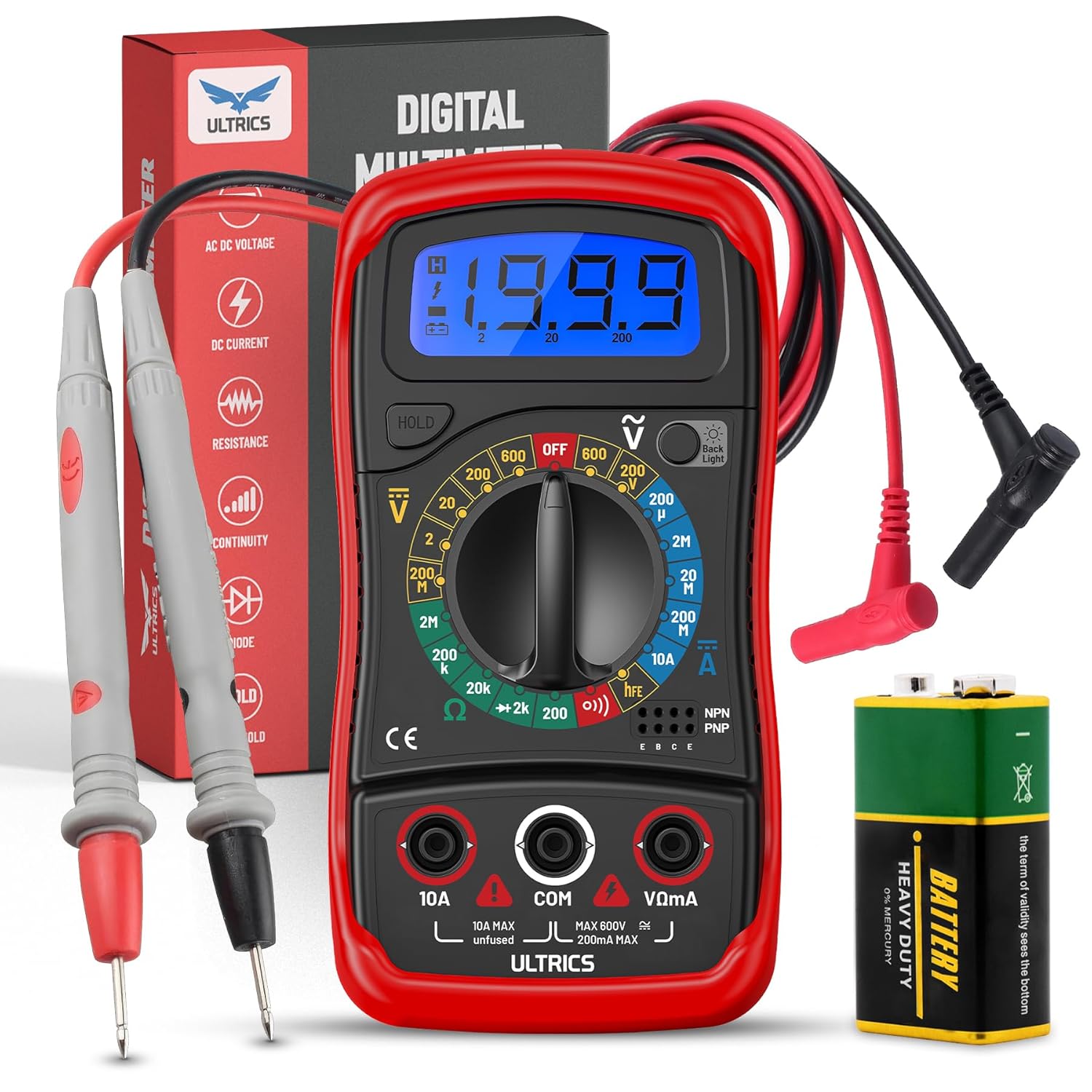
Image: Contents of the ULTRICS Digital Multimeter D2 package, including the multimeter, red and black test leads, and a 9V battery.
Produkt overview
Familiarize yourself with the components of your ULTRICS Digital Multimeter D2.

Image: Detailed diagram of the ULTRICS Digital Multimeter D2, highlighting its key components such as the LCD display, data hold button, backlight button, function switch, test lead jacks, and protective rubber shell.
- LCD-skærm: Shows measurement readings, units, and polarity. Features a bright backlight for low-light conditions.
- Datahold-knap: Freezes the current reading on the display for easier recording.
- Baggrundslys knap: Aktiverer eller deaktiverer displayets baggrundsbelysning.
- Function Switch (Rotary Dial): Vælger den ønskede målefunktion og -område.
- 10A indgangsstik: Used for measuring DC current up to 10 Amperes.
- COM (Common) Input Jack: The negative (-) input for all measurements. Always connect the black test lead here.
- VΩmA Input Jack: The positive (+) input for voltage, resistance, and milliampere current measurements. Connect the red test lead here.
- Transistor Test Jacks (hFE): Used for testing NPN and PNP transistors.
- Protective Rubber Shell: Provides durability and protection against minor impacts and splashes.
- Sammenfoldelig støtte: Allows for hands-free operation and easy viewvinkel.
Opsætning
Installation af batteriet
The ULTRICS Digital Multimeter D2 requires one 9V battery (included).
- Find batterirummet på bagsiden af multimeteret.
- Brug en skruetrækker til at fjerne skruen, der fastgør batteridækslet.
- Fjern forsigtigt batteridækslet.
- Connect the 9V battery to the battery clips, ensuring correct polarity (+ to + and - to -).
- Place the battery inside the compartment.
- Sæt batteridækslet på igen og fastgør det med skruen.
Tilslutning af prøveledninger
Sørg altid for, at testledningerne er sikkert tilsluttet, før du foretager målinger.
- Insert the black test lead's banana plug into the KOM (Fælles) indgangsstik.
- For de fleste målinger (volumentage, resistance, continuity, diode, small current), insert the red test lead's banana plug into the VΩmA indgangsstik.
- For high current measurements (up to 10A DC), insert the red test lead's banana plug into the 10A indgangsstik.
Betjeningsvejledning
This section details how to perform various measurements using your multimeter.
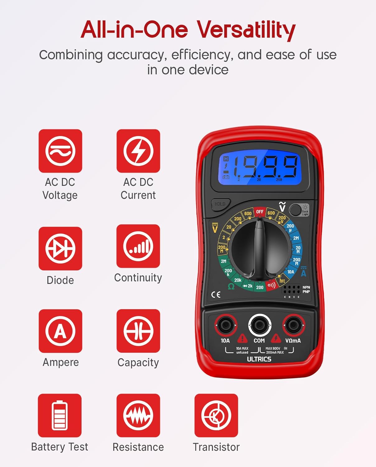
Image: Visual representation of the multimeter's versatile functions, including AC/DC Voltage, AC/DC Current, Diode, Continuity, Ampere, Capacity, Battery Test, Resistance, and Transistor measurements.
Måling DC Voltage (VDC)
- Tilslut den sorte testledning til KOM stik og den røde testledning til VΩmA stik.
- Turn the function switch to the desired VDC range (e.g., 200mV, 2V, 20V, 200V, 600V). If unsure, start with the highest range and decrease as needed.
- Tilslut testledningerne parallelt på tværs af den komponent eller det kredsløb, der skal måles.
- Læs bindtage -værdi på LCD -displayet.
Måling AC Voltage (VAC)
- Tilslut den sorte testledning til KOM stik og den røde testledning til VΩmA stik.
- Turn the function switch to the desired VAC range (e.g., 200V, 600V).
- Tilslut testledningerne parallelt over AC-volumentage kilde.
- Læs bindtage -værdi på LCD -displayet.
Measuring DC Current (ADC)
FORSIGTIGHED: Never connect the multimeter in parallel when measuring current. Always connect it in series with the circuit. Improper connection can damage the multimeter or the circuit.
- Sluk for strømmen til kredsløbet.
- For currents up to 200mA, connect the black test lead to the KOM stik og den røde testledning til VΩmA stik.
- For currents up to 10A, connect the black test lead to the KOM stik og den røde testledning til 10A stik.
- Turn the function switch to the desired ADC range (e.g., 200µA, 2mA, 20mA, 200mA, 10A).
- Break the circuit and connect the multimeter in series with the circuit.
- Turn on power to the circuit.
- Aflæs den aktuelle værdi på LCD-displayet.
- Turn off power to the circuit before disconnecting the multimeter.
Measuring Resistance (Ω)
FORSIGTIGHED: Ensure the circuit is completely de-energized before measuring resistance. Measuring resistance on a live circuit can damage the multimeter.
- Tilslut den sorte testledning til KOM stik og den røde testledning til VΩmA stik.
- Turn the function switch to the desired Ω range (e.g., 200Ω, 2kΩ, 20kΩ, 200kΩ, 2MΩ, 20MΩ).
- Tilslut testledningerne på tværs af den komponent, hvis modstand du vil måle.
- Aflæs modstandsværdien på LCD-displayet.
Kontinuitetstest
The continuity test checks for a complete circuit path. An audible buzzer will sound if continuity is detected.
- Tilslut den sorte testledning til KOM stik og den røde testledning til VΩmA stik.
- Drej funktionskontakten til Kontinuitet (buzzer) position.
- Tilslut testledningerne på tværs af kredsløbet eller komponenten.
- Hvis modstanden er under cirka 50Ω, lyder summeren, hvilket indikerer kontinuitet.
Diodetest
Diodetesten måler fremad voltagen dråbe af en diode.
- Tilslut den sorte testledning til KOM stik og den røde testledning til VΩmA stik.
- Drej funktionskontakten til Diode position.
- Connect the red test lead to the anode (+) and the black test lead to the cathode (-) of the diode.
- Læs videre bindtage drop on the LCD display. Reverse the leads; the display should show "OL" (Overload) for a good diode.
Transistor hFE test
This function tests the DC current gain (hFE) of NPN and PNP transistors.
- Drej funktionskontakten til hFE position.
- Identify the Emitter (E), Base (B), and Collector (C) leads of the transistor.
- Insert the transistor leads into the corresponding holes in the hFE socket on the multimeter, ensuring correct NPN or PNP type.
- Read the hFE value on the LCD display.
Data Hold-funktion
Tryk på HOLDE knappen for at fryse den aktuelle aflæsning på displayet. Tryk igen for at slippe holdeknappen og genoptage live-aflæsningerne.
Baggrundsbelysningsfunktion
Tryk på Baggrundsbelysning button to turn the LCD backlight on or off, improving visibility in dim environments.

Billede: Et nærbillede view of the multimeter's LCD display, demonstrating its bright backlight feature for enhanced readability in various lighting conditions.
Opretholdelse
Rensning
For at rengøre multimeteret skal du tørre huset af med enamp cloth and a mild detergent. Do not use abrasives or solvents, as these may damage the casing eller display.
Udskiftning af batteri
When the low battery indicator appears on the display, replace the 9V battery as described in the "Installing the Battery" section to ensure continued accurate readings.
Udskiftning af sikring
If the current measurement function stops working, the fuse may need replacement. This multimeter is equipped with internal fuses for protection.
- Ensure the multimeter is OFF and all test leads are disconnected.
- Fjern batteridækslet og batteriet.
- Carefully open the main casing (this may require removing additional screws, typically located under the rubber shell).
- Locate the fuse(s) on the circuit board. This model typically uses a 200mA/250V fuse for the mA range and a 10A/250V fuse for the 10A range.
- Replace the blown fuse with a fuse of the same type and rating. Never use a fuse with a different rating.
- Reassemble the multimeter, ensuring all screws are tightened and the casing er korrekt forseglet.
Opbevaring
If the multimeter is not used for a long period, remove the battery to prevent leakage and store the device in a cool, dry place, away from direct sunlight and extreme temperatures.
Fejlfinding
| Problem | Mulig årsag | Løsning |
|---|---|---|
| Intet display eller svagt display | Tæt eller lavt batteri | Udskift 9V batteriet. |
| "OL" (Overbelastning) vises | Input value exceeds selected range; open circuit (for resistance/continuity) | Select a higher range; check for breaks in the circuit or component. |
| Forkerte aflæsninger | Forkert funktion/område valgt; dårlig testledningsforbindelse; lavt batteri | Verify function switch position and range; ensure leads are firmly connected; replace battery. |
| Strømmåling virker ikke | Sprunget sikring | Udskift den relevante sikring (se afsnittet Vedligeholdelse). |
| No continuity buzzer | Open circuit; resistance too high | Ensure circuit is closed; check resistance value (buzzer typically activates below 50Ω). |
Specifikationer
| Feature | Detalje |
|---|---|
| Model | Digital Multimeter D2 |
| Vise | 3 ½ digit LCD, 1999 counts, with backlight |
| DC bindtage | 200mV / 2V / 20V / 200V / 600V |
| AC Voltage | 200V / 600V |
| DC-strøm | 200µA / 2mA / 20mA / 200mA / 10A |
| Modstand | 200Ω / 2kΩ / 20kΩ / 200kΩ / 2MΩ / 20MΩ |
| Diodetest | Ja |
| Kontinuitet Buzzer | Ja |
| Transistor hFE test | Ja |
| Datahold | Ja |
| Strømkilde | 9V batteri |
| Sikkerhedsvurdering | IEC CAT II 600V, CE, RoHS compliant |
| Dimensioner (L x B x H) | 14.6 x 10 x 5 cm (5.75 x 3.94 x 1.97 tommer) |
| Vægt | 240 gram (0.53 lbs) |
Garanti og support
ULTRICS provides a 12-month warranty for this product, covering manufacturing defects from the date of purchase. Please retain your proof of purchase for warranty claims.
For technical support, warranty claims, or any questions regarding your ULTRICS Digital Multimeter D2, please contact ULTRICS customer service through the retailer's platform or the official ULTRICS webwebsted. Hav venligst dine købsoplysninger og modelnummer klar, når du kontakter support.
Fabrikant: ULTRICS
Modelnummer: Digital Multimeter D2
ASIN: B0DYP62MW7