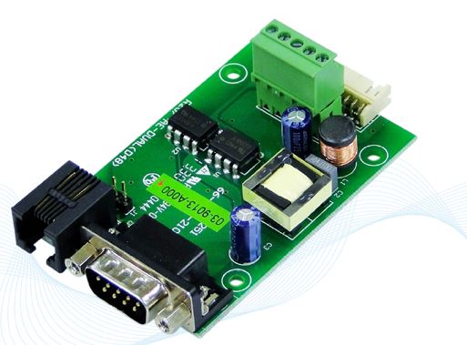
COTEK CT-201 Communication Interface Module
Features
- Support COTEK Programmable Series power supply (Excluding AK & AEK-3000 ORing Series)
- Support max. 8 units parallel control function
- Support RS232/485 protocol
- Easy installation for parallel control.
Specification
- Input Voltage: 5Vdc
- Operating Temperature Range: -10℃ ~ 60℃
- Storage Temperature Range: – 30℃ ~ 70℃
- Baud rate: 4800, N, 8, 1
- Connector: DB-9F fo RS232, RJ-11 (6P4C) for RS485
- Optical Isolation: I/P – O/P: 2500Vac rms for 1 minute
Mechanical dimension

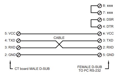
CT cable drawing
- CT-201 / CT-204 Cable (COTEK Part no.47-0124-0001)
| Mating Housing / Contact | |
|
JST PHDR-24VS or equivalent | JST SPHD-002T-P0.5 or equivalent |

- CT-251 / CT-551 Cable (COTEK Part no.47-0112-0021)
| Mating Housing / Contact | |
| JST PHDR-24VS or equivalent | JST SPHD-002T-P0.5 or equivalent |

WARNING!

- CT parallel cable (For CT-551 Only) (COTEK Part no. 47-0106-0003)

WARNING!
DO NOT use standard telephone cable
- CT-204 to CT-204 parallel cable (Optional) (COTEK Part no. 47-0103-0028)

Accessories
| Accessories MODEL | User Guide | CT-201 / CT-204 cable | CT-251 / CT-551 cable | CT parallel cable | EC350R-05P connector | CT-204 to CT-204 cable |
| CT-201 | 1 | 1 | — | — | 1 | — |
| CT-204 | 1 | 4 | — | — | — | Optional |
| CT-251 | 1 | — | 1 | — | 1 | — |
| CT-551 | 1 | — | 1 | 1 | 1 | — |
Pin assignment
- DB-9F RS232 (only for CT-201/204/251)
| 1 | NC |
| 2 | RxD |
| 3 | TxD |
| 4 | NC |
| 5 | GND |
| 6 | NC |
| 7 | NC |
| 8 | NC |
| 9 | NC |
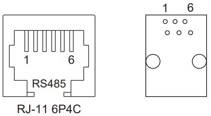
- RJ-11 6P4C RS485 (only for CT-251/551)
| 1 | NC |
| 2 | GND |
| 3 | DATA + |
| 4 | DATA – |
| 5 | +5V |
| 6 | NC |
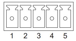
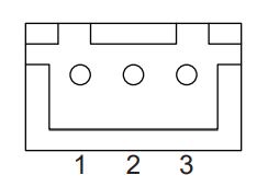
- ECH350V-05P DINKLE (only for CT-201/251/551)
| 1 | GND |
| 2 | AUX |
| 3 | PAR |
| 4 | VS – |
| 5 | VS + |
- B-XH-A 180’C (only for CT-204)
| 1 | GND |
| 2 | RxD |
| 3 | TxD |
- Control Pin connections: JST S24B-PHDSS or equivalent
| Pin No. | Assignment | Pin No. | Assignment | Pin No. | Assignment | Pin No. | Assignment | Pin No. | Assignment |
| 1 | VS+ | 6 | GND | 11 | EN+ | 16 | GND | 21 | AUX |
| 2 | VO+ | 7 | PAR | 12 | AUX | 17 | AUX | 22 | GND |
| 3 | VS- | 8 | VSET | 13 | ACI | 18 | GND | 23 | NC. |
| 4 | VO- | 9 | EN- | 14 | GND | 19 | SCL | 24 | NC. |
| 5 | POK | 10 | GND | 15 | VCI | 20 | SDA |
CT Series Quick Feature Guide
| Function MODEL | Parallel / Remote sense | To Host | Power Connection | RS485 Expansion | RS232 Expansion |
| CT-201 | RS-232(DB-9F) | 1 Unit | |||
| CT-204 | RS-232(DB-9F) | 4 Units | |||
| CT-251 | RS-232(DB-9F) | 1 Unit | |||
| CT-551 | — | 1 Unit |
Application Notes
MODEL: CT-201

MODEL: CT-204 Control 8 EUT in parallel condition.

MODEL: CT-251 / 551 Parallel Control with Remote Sensing

Before using RS232/485 to control COTEK programmable SMPS (excl. AK Series), make sure to read the following notes:
- Make sure the voltage and current setting has been correctly delivered to EUT before setting the command (Power ) to turn on / off the power supply. If OVP or OLP LED signal has been activated due to incorrect operation, entering the command POWER will allow you to operate the EUT and setting command.
- Every RS232/485 command character must be entered within 400ms, the ending point is judged by CR LF (0D0A), program will disregard the command if the command entering time exceeds 400ms per character.
- After shut-down of the power of EUT, the command setting will return to default, local mode.
- After power on the EUT with command execution is complete, EUT will switch to remote mode with an orange LED signal status. For detailed LED signal info, please refer to the EUT datasheet.
- Please refer to the CT-xxx user manual (Page 02) for the cable spec. connect in between the CT-xxx controller board and EUT. Make sure to connect the cable as instructed in the user manual to avoid CT-xxx damage.
- CT-xxx boards could support max. 8 units parallel control function (ADDS0-7). Before controlling the EUT, make sure the address is not in conflict with each other.
- When controlling multiple EUTs, make sure to query the Address (ADDS x) first before entering a command to avoid EUT retrieving the incorrect value. If only a single EUT, there is no need to query ADDS before entering the command.
Documents / Resources
 | COTEK CT-201 Communication Interface Module [pdf] User Guide CT-201, CT-204, Communication Interface Module, Communication Interface, Interface Module, CT-201, Module |


