Cascoda KNX IoT Development Board

Product Information
Specifications
- USB or UART connectivity
- 5V or 3.3V supply options
- 3.7V Li/LiPo battery integration with charging from a 5V supply or USB
- Two Mikroelektronika ClickTM slots for plug-in sensor/actuator connectivity
- Integrated chip antenna and an external antenna option
- Dimensions: 66 x 64mm
Product Usage Instructions
Setup and Configuration
To begin using the device as a Colour Actuator, follow these steps:
- Install and commission the device according to the provided instructions.
- Once fully installed, the device will operate as an RGB colour actuator.
Control Commands
The device can react to the following commands sent by another KNX entity:
- On/Off
- InfoOnOff (feedback)
- Setting of RGB – Current RGB value (feedback)
- Setting of absolute dimming value – Current dimming value (feedback)
- Scene Control
Using appropriate controllers, you can control the status (on/off), brightness, and color of the device, as well as store and activate scenes.
Frequently Asked Questions (FAQ)
- Q: Can the device be operated with a battery?
A: Yes, the device supports ultra-low-power battery operation and battery charging. - Q: What are the available supply options for the device?
A: The device supports both 5V and 3.3V supply options. - Q: How can I integrate plug-in sensors/actuators with the device?
A: The device features two Mikroelektronika ClickTM slots for a wide range of plug-in sensor/actuator connectivity.
Colour Actuator RGB Demo
Manual
Using the Devboard as a Colour Actuator Demo
Once the device is fully installed and commissioned, it operates as an RGB colour actuator. It can react to the following commands, sent by another KNX entity (e.g. a Colour Setting Sensor RGB, or the ETS group monitor):
- On/Off
InfoOnOff (feedback) - Setting of RGB
Current RGB value (feedback) Setting of absolute dimming value Current dimming value (feedback) Scene Control
Therefore, using appropriate counterpart controllers, you can control the status (on/off), brightness and colour of the device, as well as storing and activating scenes.
NOTE! Do not power the board with a battery when using this demo. Instead, power via USB.
Demo Overview and Requirements
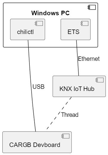
The Demo consists of controlling the CARGB using the Group Monitor on ETS. In order to do this, you will need the following:
Hardware requirements
- A Windows PC
- A Thread Border router. Cascoda recommends using the KNX IoT Hub. A development board with jumpers provided
- LED Driver 3 Click
- USB-A to Micro-USB cable
Software requirements
- ETS version 6.2.2 or later Cascoda Windows Tools An application binary
- A serial number binary
- A project file to load into ETS
This manual will show you how to set up the hardware, flash the device, commission it onto the Thread network and onto KNX, and then finally being able to control it using ETS.
General information
Document Version information
This manual is amended periodically and will be brought into line with new software releases. The change status (date) can be found in the contents header. If you have a device with a later software version, please check www.cascoda.com to find out whether a more up-to date version of the manual is available.
Used Terms
Sign Description
- DANGER! Indicates an immediately hazardous situation which will lead to death or severe injuries if it is not avoided.
- CAUTION! Indicates a potentially hazardous situation which may lead to trivial or minor injuries if it is not avoided.
- WARNING! Indicates a situation which may lead to damage to property if it is not avoided.
- NOTE! Indicates a situation which may lead to possible (known) side effects.
NOTE! Indicates a situation which may lead to possible (known) side effects.
Safety instructions
- Not applicable.
- Issues
Questions about the product?
You can reach the technical service of Cascoda under Tel. +44 (0)2380 638 111 or support@cascoda.com. We need the following information to process your service request:
- Type of appliance (model name or item number)
- Description of the problem
- Serial number or software version
- Source of supply (dealer/installer who bought the device from Cascoda )
For questions about KNX functions:
- Version of the device application
- ETS version used for the project
Contact information
- info@cascoda.com
- Threefield House,
- Threefield Lane, Southampton,
- SO14 3LP, UK
Setup and Configuration
Device Startup
The device starts up when plugged in via USB. As a reminder, do not use the battery for this demo.
Hardware Setup
NOTE! Do not power the board with a battery when using this demo. Instead, power via USB. For this demo, you will need the following hardware:
- Development board with jumpers provided
- LED Driver 3 Click
- USB-A to Micro-USB cable
To set up the hardware, follow the following steps:
- When using the KNX IoT Development board, the jumpers need to be placed in the correct position, and this differs from application to application, as well as depending on which means of power is provided. For this demo, please make sure that your jumper configuration exactly matches what is shown in the picture below (see the arrows pointing to the red blocks, which represent the jumpers). Also, make sure that none of the jumpers are loose.

- Place the LED Driver 3 Click, as shown in the pictures at the front page of this document. The rounded part of the Click should face the battery slot. You can insert the Click board on the right or left slot, both are the same.
- Connect the USB cable into the USB port on the development board.
Flashing the Firmware
Make sure you have the following before getting started:
- An installation of Cascoda’s Windows Tools. Please download CascodaWindowsTools.zip and run the installer within. Two of the tools will be necessary for this guide, namely chilictl.exe and serial-adapter.exe. NOTE: By default, these tools are added to your PATH, enabling their execution in a shell in any directory. However, if this did not occur, you will only be able to execute the tools from within the directory in which they are installed. The default installation directory is C:\Program
- Files(x86)\Cascoda Windows Tools.
- The application binary knx_colour_actuator_reed.bin for the CARGB demo.
- The serial number binary 029B00000241.bin for the CARGB demo.
Once you have all of the above, follow the steps below:
- Connect the development board to a Windows PC via USB.
- Determine the development board’s unique serial number (note: this is unrelated to the KNX serial number, which we talk about in the rest of this document), by using the Cascoda Windows Tool chilictl.exe, using the command shown below. Note that this will list all connected devices, so if you have multiple devices and want to identify which one is the devboard, then run the command once with the devboard disconnected, then again with it connected, so that you can identify the new one that appears:

- Flash the application binary knx_colour_actuator_reed.bin using chilictl.exe. Use the command shown in the picture below. The number that comes after -s should be the serial number that you have identified in the previous step.

- Double check that the application binary is now flashed onto the device, by running the same command as step 2, and making sure that the “App” name is “knx_colour_actuator_reed”.
- Flash the serial number binary 029B00000241.bin using chilictl.exe, with the command shown below.
NOTE! This serial number binary should only be flashed on 1 device per network partition. If two or more devices on the same Thread network have been flashed with this serial number binary, the demo won’t work. If you need to have multiple CARGB devices on the same network, please contact us so that we can provide you with a different unique serial number.
Your device is now ready to start the commissioning process!
Commissioning
- After powering the device using the USB cable, the device will enter a commissioning phase. Thread commissioning needs to be done first, since this will enable IPv6 communication. Next, KNX commissioning needs to be done using ETS (version ETS 6.2.2 or later).
- For both Thread and KNX commissioning, the QR code below will be needed.
 Check out the youtube video here, demonstrating the process of doing Thread and KNX Commissioning using a QR code scanner.
Thread Commissioning
Thread commissioning is adding the device to the thread network. To be able to do so, one needs to have a Thread Border router. Cascoda recommends using the KNX-IOT-HUB.
NOTE: The steps below assume that you already have a Thread network set up using the KNX IoT Hub. If you don’t, then click here for instructions on how to do that (follow the part regarding using the Web UI).
- Hover over “Thread” in the menu bar at the top, and click on “Add Device”.
- There is an input field to put QR code information. Using a QR code scanner, scan the QR code provided in this manual and then click “Submit”.

- Now wait for the device to join the Thread network. When it does, you will see it show up in the “Neighbors” table.

NOTE: The above steps are enough to move forward with the demo. See here for more details about Thread commissioning.
KNX Commissioning
KNX commissioning is adding the device to an ETS project. Since KNX IoT is a secure KNX protocol, one needs to have the security credentials and the serial number of the device. This information is contained in the QR code.
The device can only be added to a KNX IoT Area or Line. When the device is added to a KNX IoT area or Line, the credentials can be supplied. ETS can scan the QR code with the camera (or 2D bar code scanner).
Adding the Device to a Topology
- Open the project provided in ETS version 6.2.2 or later.
- Open the “Devices” panel, and select the device that you will use for this demo. In the “Properties” section on the right, click “Add Device Certificate”. A window will pop up, with an input field for the QR code information. Use a QR code scanner to scan the QR code provided in this manual. (There is also an option to use a camera).

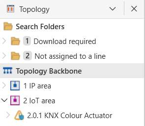
- Open a “Topology” panel. Drag and drop the device into an IoT area.
Creating a Configuration
These steps create the group objects that will be used in the s-mode messages. By linking the group objects to the communication objects (data points), one can send s-mode messages to actuators, and receive s-mode messages from sensors.
- Open a “Group Addresses” panel.
- Select “Group Addresses”, right click, select “Add Main Groups”, click OK.
- Select the newly created main group, right click, select “Add Middle Groups”, click OK.
- Select the newly created middle group, right click, select “Add Group Addresses”, increase the count to however many group addresses you want (e.g. the same as the number of Group Objects that you would like to link), then press “OK”.
- Now open the “Group Objects” tab for your device, and link each group object that you want by right clicking, “Link with…”, and then selecting the group address.

Downloading the ETS configuration
The downloading of the configuration can happen when the ETS data for the device is created, i.e.:
- The parameters are set
- The communication objects are connected
This has already been done with the previous two steps. Therefore, you can now download the configuration by selecting the device in the “Devices” panel, right click, hover over the “Download” option, and click “Download All”. After waiting a few seconds, there will be a popup asking you to either:
- download by serial number
- download with programming mode
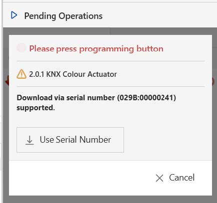
- The download by serial number does not require any interaction with the device. All you have to do is click on the “Use Serial Number” button.
- The download with programming button requires pressing the programming button. The PROG button is the SW4 button, which needs to be held down for 1 second. While the
- PROG button is pressed, the LED is on. When the PROG button is released and the device is in programming mode the LED will start blinking. Disabling the programming mode can achieved by holding down the PROG button again for 1 second.
- NOTE: The device has to be attached to a Thread network in order for it to enter programming mode. In case you are unable to put the device into programming mode, double check that it is indeed attached to a Thread network. And also make sure you are not releasing the button too soon (hold it down for > 1 second).
- Once the download is complete, the device becomes fully operational and functional.
Resetting the device
- NOTE! This section is informational. If you are simply following the steps to run the Demo with ETS, please do not reset the device!
- The device allows resetting of KNX and Thread in separate steps. This allows that the KNX configuration can be reset to factory default, without resetting the connectivity part.
Reset KNX
- Reset of KNX is achieve by pressing the PROG button for 5 seconds. While the PROG button is pressed, the LED is on.
When the PROG button is released (after 5 sec), the LED will quickly flash 2 times. - NOTE! KNX Reset: this means that also the security credentials are removed. Hence ETS will download newly created device keys.
Reset Thread
- Reset of Thread is achieve by pressing the PROG button for 10 seconds. While the PROG button is pressed, the LED is on. When the PROG button is released (after 10 sec), the LED will slowly flash 3 times.
- NOTE! Thread Reset: This means that the device needs to be added to the thread network again.
Running the Demo with ETS
- You can run a demo using only 1 CARGB device and ETS. The Group Monitor can be used as a controller, sending messages to the configured datapoints on the device, and thus causing the device to behave as if it were receiving those same messages from another KNX IoT counterpart device.
- NOTE: This section assumes that you have followed the Thread Commissioning and KNX Commissioning steps, and thus have already downloaded a configuration to your device using ETS.
With that being said, follow the steps below to control the CARGB:
- Open the Group Monitor (Panels > Diagnostics > Group Monitor), and click “Start”.
- To switch the LED of the CARGB device ON, select the Group Address linked with the “CARGB OnOff” Group Object, change the “Value” to “On”, and click “Write”. The LED on CARGB device should now be ON, with a certain colour.

- To increase or decrease the brightness, select the Group Address linked with the Group Object “CARGB AbsDimVal”, set the desired percentage value, and click “Write”.

- To change the colour of the LED on the CARGB device, select the Group Address linked with the Group Object “CARGB SetRGB”, use the colour picker to select a colour, and press “Write”. The LED on the device will match the colour that you picked using the colour picker!

Software Bill of Materials
This paragraph contains the list of used open source software in this product.
- Name Version License
- Cascoda SDK 0.25 BSD-3-Clause
- tinycbor v0.6.0 MIT
- mbedtls 2.16.2 Apache-2.0
- Openthread knx-v1.0.0 BSD-3-Clause
Cascoda SDK
- Description: Cascoda development
- License: BSD-3-Clause
- Version: 0.25
- URL: https://github.com/Cascoda/cascoda-sdk
- Notes: Chili2D/S SDK, various drivers
tinycbor
- Description: CBOR implementation License: MIT
- Version: v0.6.0
- URL: https://github.com/intel/tinycbor Notes: used for CBOR encoding/decoding
mbedtls
- Description: security constructs
- License: Apache-2.0
- Version: 2.16.2
- URL: https://github.com/ARMmbed/mbedtls Notes: used for encryption/decryption
Openthread
- Description: OpenThread, IPv6
- License: BSD-3-Clause
- Version: knx-v1.0.0
- URL: https://github.com/Cascoda/openthread Notes: Cascoda’s port of OpenThread
KNX device information
- Info Field Value
- Manufacturer cascoda
- Model KNX Colour Actuator
- Order_number
- Hardware_type 000000000000
- Hardware version [0, 0, 1]
- Firmware version [0, 0, 1]
- Sleepy Device No
Interfaces
- Type Direction Communication Flags Description
- if.a Input RW.U. Actuator, hardwared actuator
- if.i Input RW.U. Input, calculated value
- if.s Output R.T.I Sensor, hardwared sensor
- if.o Output R.T.I Output, calculated value
NOTE! Communication Flags UI are disabled by default.
NOTE! Communication Flag C is not part of KNX IoT.
Colour Actuator Demo status: 0.0.1 12/08/2024, 14:05
Data points
url name instance resource type interface type data type
| “/p/o_1_1” | CARGB_OnOff | 1 | 423.51 | if.a | DPT_Switch |
| “/p/o_2_2” | CARGB_InfoOnOff | 1 | 423.80 | if.s | DPT_Switch |
| “/p/o_3_3” | CARGB_SetRGB | 1 | 423.52 | if.a | DPT_Colour_RGB |
| “/p/o_4_4” | CARGB_CurrRGB | 1 | 423.81 | if.s | DPT_Colour_RGB |
| “/p/o_5_5” | CARGB_AbsDimVal | 1 | 423.3090 | if.a | DPT_Scaling |
| “/p/o_6_6” | CARGB_ActualDimmingValue | 1 | 423.3091 | if.s | DPT_Scaling |
| “/p/o_7_7” | Scene_Control | 1 | 1010.54 | if.a | DPT_SceneControl |
Parameters
No parameters defined.
© Cascoda Ltd. 2024, All Rights Reserved.
Documents / Resources
 | Cascoda KNX IoT Development Board [pdf] User Manual KNX IoT Development Board, IoT Development Board, Development Board, Board |
 | CASCODA KNX IoT Development Board [pdf] Instruction Manual KNX IoT Development Board, IoT Development Board, Development Board, Board |
 | Cascoda KNX IoT Development Board [pdf] Installation Guide KNX IoT Development Board, IoT Development Board, Development Board |
 | Cascoda KNX IoT Development Board [pdf] Instruction Manual KNX IoT Development Board, KNX IoT, Development Board, Board |


