FNIRSI LCR-P1
FNIRSI LCR-P1 tester tranzistora
Uputstvo za upotrebu
Uvod
Thank you for choosing the FNIRSI LCR-P1 Transistor Tester. This compact and multifunctional device is designed for precise measurement and analysis of a wide range of electronic components, including transistors, diodes, capacitors, resistors, and inductors. It also features infrared decoding capabilities, making it an indispensable tool for electronics enthusiasts, engineers, and technicians. This manual provides detailed instructions for safe and effective operation of your LCR-P1.
Sigurnosne informacije
Please read and understand all safety warnings and operating instructions before using the device to prevent injury or damage to the tester.
- Pražnjeni kondenzatori: Always ensure that any capacitors are fully discharged before connecting them to the tester. Although the LCR-P1 features anti-burning protection with automatic discharge, pre-discharging high-voltage capacitors is a critical safety measure to prevent damage to the device or injury.
- Izvor napajanja: Use only the provided Type-C cable for charging. Do not use damaged cables or power adapters.
- Radno okruženje: Operate the device in a dry, clean environment. Avoid exposure to moisture, extreme temperatures, or corrosive substances.
- Rukovanje: Pažljivo rukujte uređajem. Izbjegavajte ispuštanje ili izlaganje jakim udarcima.
- Održavanje: Ne pokušavajte rastavljati ili modificirati uređaj. Za sve servisne radove obratite se kvalificiranom osoblju.
Product Overview
The FNIRSI LCR-P1 is designed for ease of use and portability. Familiarize yourself with its components:
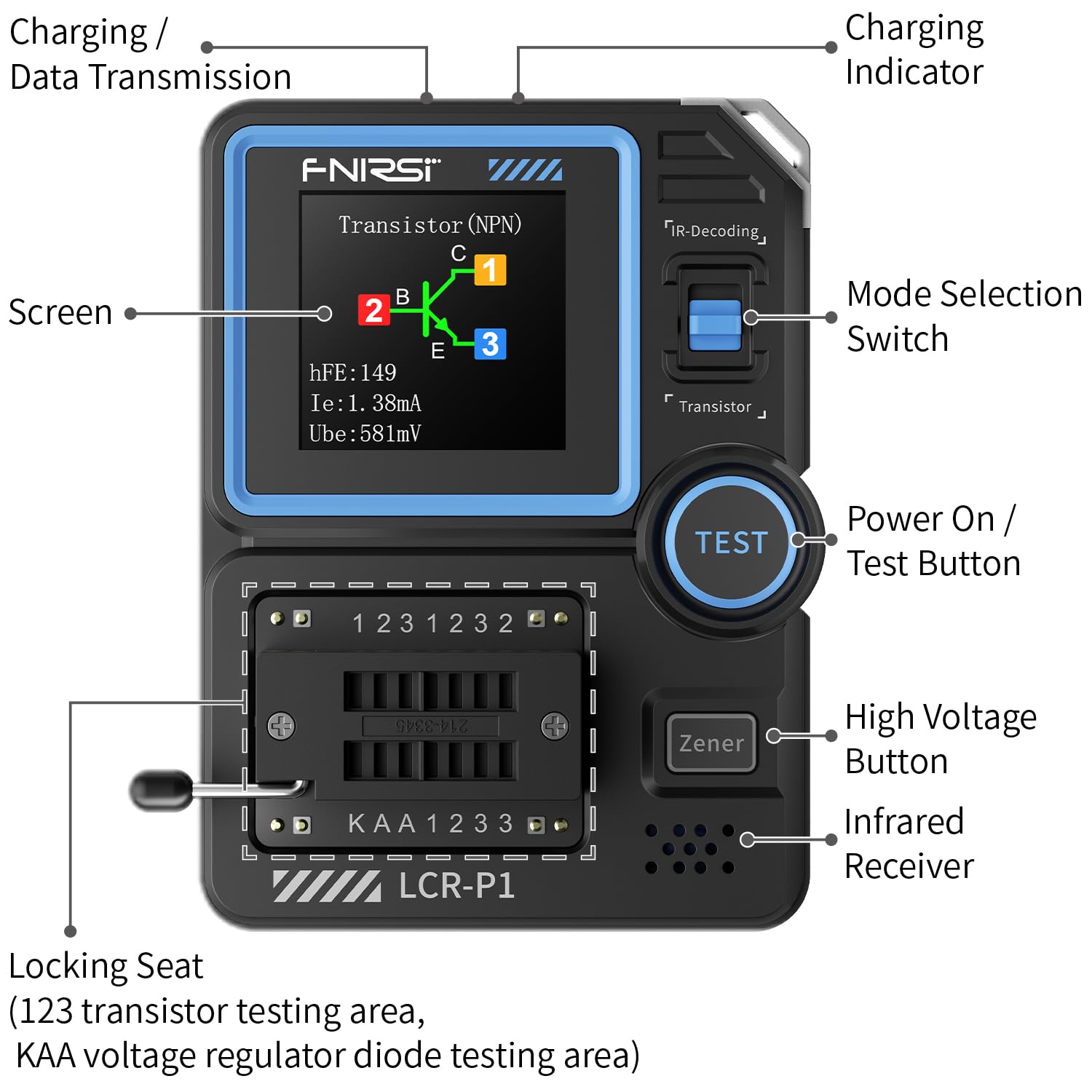
This image displays the FNIRSI LCR-P1 Transistor Tester, highlighting its key components. The screen shows measurement results, while the Type-C charging port is located on the side. The mode selection switch and test button are on the top right. Below the test button are the high voltage button and infrared receiver. The locking seat, designed for testing various components, is prominently featured at the bottom.
Ključne karakteristike:
- Transistor and Component Testing: Measures NPN, PNP, triode, MOS, FET, diodes, Zener diodes, capacitors, resistors, inductors, and batteries.
- Dizajn prilagođen korisniku: Features a 1.45-inch full-color screen for clear display, a 300mAh built-in battery, and a Type-C interface for charging and data transfer.
- Anti-Burning Protection: Automatically discharges uncharged capacitors upon insertion to prevent damage to the device or component.
- NEC Infrared Waveform Analysis: Supports NEC infrared protocol code analysis, useful for debugging and maintenance of remote control devices.
- Intelligent Automatic Detection: Automatically detects component pin definitions and parameters, significantly improving work efficiency.
Setup
Punjenje uređaja:
Before first use, fully charge the LCR-P1. Connect the provided Type-C USB cable to the charging port on the side of the device and plug the other end into a standard USB power adapter (not included) or a computer USB port. The charging indicator on the device will show the charging status.

The image shows the FNIRSI LCR-P1 Transistor Tester being charged via its Type-C port. The device has a built-in 300mAh battery, and the Type-C interface also supports data transfer for firmware upgrades.
Initial Component Connection:
The LCR-P1 comes with interchangeable test boards to accommodate different component types. Select the appropriate test board for your component (e.g., ZIF socket for through-hole components or SMD test pads for surface-mount devices). Insert the component into the designated pins on the test board, ensuring a secure connection.

This image illustrates the FNIRSI LCR-P1 Transistor Tester with its two included test boards. One board is designed for testing small surface-mount device (SMD) components, while the other is for larger through-hole components, enhancing the tester's adaptability for various electronic parts.
Uputstvo za upotrebu
Basic Component Testing:
- Uključeno: Press the 'TEST' button to power on the device.
- Umetni komponentu: Carefully insert the component into the appropriate test socket (ZIF socket or SMD pads). Ensure good contact.
- Pokreni test: Press the 'TEST' button again to start the measurement. The device will automatically identify the component type and display its parameters on the screen.
- Pročitajte rezultate: The screen will show the component type (e.g., NPN, PNP, Resistor, Capacitor), pinout diagram, and measured values (e.g., hFE, capacitance, resistance, inductance).

The main image shows the FNIRSI LCR-P1 Transistor Tester in operation, displaying the test results for an NPN transistor. The screen clearly indicates parameters such as hFE, Ie, and Ube. Various test leads and the ZIF (Zero Insertion Force) socket for component insertion are also visible.
Zener Diode Test:
The LCR-P1 can test Zener diodes within a measurable range of 0.01V to 32V. Insert the Zener diode into the designated Zener test area (KAA voltage regulator diode testing area) and press the 'Zener' button to initiate the test. The device will display the Zener voltage.

This image shows the FNIRSI LCR-P1 Transistor Tester conducting a Zener diode test. The display indicates the measurable range for Zener diodes, which is 0.01-32V, demonstrating the device's capability for this specific component.
Infrared Decoding:
To use the infrared decoding function, switch the mode selection switch to 'IR-Decoding'. Point an infrared remote control towards the infrared receiver on the LCR-P1 and press a button on the remote. The tester will display the decoded NEC infrared protocol code, including address and command codes.

The image illustrates the infrared decoding function of the FNIRSI LCR-P1 Transistor Tester. The screen shows decoded infrared signals, including the address code and command code, which is beneficial for debugging and analyzing remote control devices.
Održavanje
- čišćenje: Za čišćenje uređaja koristite meku, suhu krpu. Ne koristite abrazivna sredstva za čišćenje ili rastvarače.
- Skladištenje: Store the LCR-P1 in a cool, dry place away from direct sunlight and extreme temperatures.
- Ažuriranja firmvera: Periodically check the official FNIRSI website for firmware updates. Updates can improve performance and add new features. Use the Type-C interface for data transfer during updates.
Rješavanje problema
If you encounter issues with your FNIRSI LCR-P1, refer to the table below for common problems and solutions.
| Issue | Mogući uzrok / rješenje |
|---|---|
| Uređaj se ne uključuje. | Ensure the device is fully charged. Connect to a Type-C power source and allow it to charge for at least 30 minutes before attempting to power on again. |
| Incorrect component readings. | Verify that the component is inserted correctly into the test pins. Ensure the component is not damaged. Try testing a known good component. Perform a self-test if available in the device menu. |
| Capacitor burning during test. | The device has built-in anti-burning protection. However, always ensure large capacitors are manually discharged before insertion to prevent any potential issues, especially with high-voltage kondenzatori. |
| Ekran je prazan ili zamrznut. | Try restarting the device by holding the 'TEST' button. If the issue persists, ensure the battery is charged. |

This image highlights the anti-burning protection mechanism of the FNIRSI LCR-P1. It shows how the device automatically discharges uncharged capacitors when inserted into the test socket, preventing potential damage to the component or the tester itself.
Specifikacije
| Parametar | Vrijednost |
|---|---|
| Model | LCR-P1 |
| Brand | FNIRSI |
| Display | 1.45-inch Full-Color Screen |
| Baterija | 300mAh Lithium Polymer Battery (Built-in) |
| Interfejs za punjenje | Tip-C |
| Dimenzije proizvoda | 8.1 x 6.5 x 2.5 cm |
| Težina proizvoda | 77.1 g |
| Preciznost mjerenja | ±5% |
| Zener Diode Test Range | 0.01V - 32V |
| Uključena dodatna oprema | LCR-P1 x 1, Patch Test Board x 1, Test Hooks x 3, Data Cable x 1, Manual x 1, Box x 1 |
Garancija i podrška
The FNIRSI LCR-P1 Transistor Tester comes with a standard manufacturer's warranty. Please refer to the warranty card included in your product packaging for specific terms and conditions. For technical support, troubleshooting assistance, or warranty claims, please contact FNIRSI customer service through their official website or the retailer from whom you purchased the product. Keep your purchase receipt as proof of purchase for warranty purposes.
Ask a question about this manual
Ask about setup, troubleshooting, compatibility, parts, safety, or missing instructions. Manuals+ will review the question and use this page’s manual context to help answer it.