

Instructions for use
![]()
1 Introduction
Congratulations on the purchase of your Smart&Easy Control Module. With this module, in combination with your Automatic, you can control any function of your pool. The connected functions can be controlled either directly via your Automatic or conveniently via the Automatic app.
![]() Please be sure to follow the “Safety Instructions” in the appendix!
Please be sure to follow the “Safety Instructions” in the appendix!
IMPORTANT: The installation of the Smart&Easy Control Module must be carried out by authorised and trained professionals (electricians).
– Please read these instructions carefully and make sure that all the necessary parts for the installation as well as all necessary tools are at hand.
– Failure to follow these instructions may result in risks to health, equipment and installation!
– The housing of the automatic device required for the connection does not need to be opened for installation.
– Be sure to observe all general and special hazard warnings when handling electronics.
– Also observe all generally applicable safety regulations. Wear protective clothing if necessary.
2 Scope of delivery
- Smart&Easy Control Module
- Antenna
- Operating instruction (this document)

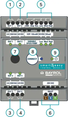
3 Connections & Specifications
The following table describes the connections and indicators:
| Number | Designation | Property |
| 1, 2, 3, 4 | Relay switching outputs: OUT 1 – 4 | 4 x NO relays, potential-free 4 A / 230 V AC / 24 V DC |
| 5 | Variable Speed Pump (VSP) outputs | 4 x Digital Relays: – 3 x NO: Eco, Normal, High – 1 x NO/NC: Stop/Run 150 mW / 35 V DC / 50 mA |
| 6 | Power supply | 230 – 240 VAC (L, N, PE) 50 – 60 Hz |
| 7 | Antenna Connector | WIFI, 2.4 GHz 1-1 pairing only with automatic device. Antenna with screw thread |
| 8 | Blue LED | Establishing a connection / pairing with Automatic – Fast flashing = device pairs – Permanenetly on = connection available – Slow Flashing = Trying to reconnect |
| 9 | Green Power LED (ON/OFF) | LED lights = Smart&Easy Control Module is switched on. |
| 10 | Power consumption | max. 5 W |
| 11 | Dimensions incl. antenna | 70 x 90 x 80 mm |
Important:
The device is powered by 230 V AC. Potential-free relays are used for the outputs OUT 1 – 4. These relays do not supply the connected equipment with 230 V AC. An external power supply, protected by the component-specific fuses, is required for these.
Via the respective green status LEDs ![]() on the top side of the Smart&Easy Control Module the operating status is displayed.
on the top side of the Smart&Easy Control Module the operating status is displayed.
Green LED lights up = active
4 Installation
– The installation of the Smart&Easy Control Module must be carried out by authorised and trained professionals (electricians).
![]() Warning: Danger to life
Warning: Danger to life
– Mounting on DIN rail (DIN rail according to EN 50022)
– Ensure good accessibility and visibility
– Protection against water and dust (control cabinet)
– Ensure sufficient signal strength for Automatic! Signal status is displayed during the connection process!
– Electrical installation must be protected by a Residual Current protective Device (RCD) 30 mA, according to local regulation
5 Electric connection of additional functions
The following installation instructions provide an overview of the various connection options. Here, various examples are used to illustrate how the Smart&Easy Control Module is connected to the various electronic components.
Important:
It must be ensured that all safety regulations are complied with during the electrical installation and that all component-specific connection specifications are observed! To do this, carefully read the operating instructions of the devices to be connected and compare them with the technical data of the Smart&Easy Control Module.
5.1 Single Speed Filter Pump (ON/OFF)
The connection of a filter pump with a fixed speed can be carried out according to the following wiring diagram.
The use of an appropriate contactor and motor circuit breaker is compulsory.

a) 230 V AC + RCD (≤ 30 mA)
(1) Motor Circuit Breaker
(2) Contactor
(3) Filter Pump
(4) Connection to OUT 1 – 4 possible
► Hint
By using a contactor, the hardware of the Smart&Easy Control Module is protected by separating the control and main circuits.
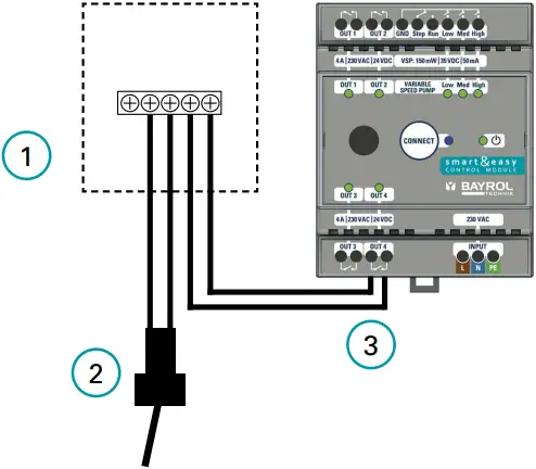
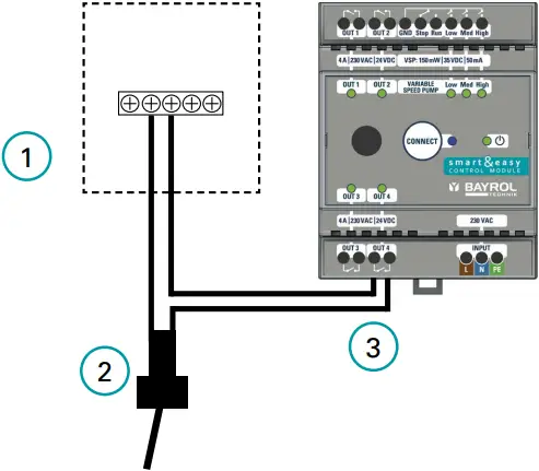
5.2 Frequency-controlled filter pump (VS pumps)
General connection diagram for illustrative purposes:

a) 230V AC + RCD (≤ 30 mA)
(1) Circuit breaker
(2) VSP Filter Pump
(3) Digital control cable of the filter pump
(4) Digital Inputs for the pump control cable
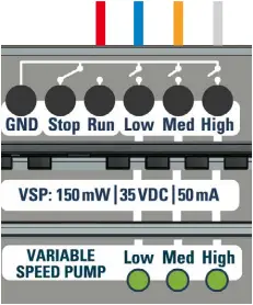
A frequency-controlled pump is connected via the digital inputs exclusively designed for this purpose :

Digital inputs: 150 mW / 35 V DC / 50 mA each
![]() The Smart& Easy Control Module can only switch to GND or “Minus”. Positive voltages (e.g. +12 V) cannot be switched!
The Smart& Easy Control Module can only switch to GND or “Minus”. Positive voltages (e.g. +12 V) cannot be switched!
![]() Attention: Outputs must not come into contact with 230 V!
Attention: Outputs must not come into contact with 230 V!
The power supply to the pump must be provided separately.
| No. | Name | Description |
| 1 | GND | Ground Connection → Already connected internally to the other terminals (no bridges required) |
| 2 / 3 | Stop (NC) / Run (NO) | Stop = closed / Run = open |
| 4 | Low | Slow pump speed |
| 5 | Med | Medium pump speed |
| 6 | High | Increased pump speed |
Depending on the pump model/manufacturer used, there are different connection scenarios to the digital inputs. The most common models are covered here and described below.
Important:
1) Frequency-controlled pumps from other manufacturers can be controlled as long as their connection logic matches that of one of the pumps described below.
In any case, always consult the pump manufacturer’s operating instructions and make sure that you have read and understood all connection instructions as well as all safety instructions.
2) Before connecting the digital input cable to the Smart&Easy Control Module, switch off the entire electrical system.
3) The digital inputs are dry contacts that must never be associated with the phase, neutral or ground of the filter cabinet’s power supply, as this can damage the pump. If you don’t need one of the wires of the cable for the external digital inputs, electrically insulate it.
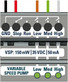
5.2.1 Speck Badu ECO
Applies to Speck BADU ECO (Touch, Touch-pro, Flow and 90 Eco VS)
| Connection table | ||
| Definition | Wire color | Connection Smart&Easy Control Module |
| n 1 | Brown | Low |
| n 2 | Green | Med |
| n 3 | White | High |
| Stop | Red | Stop |
| GND/ common | Black | GND |
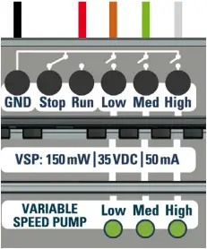
5.2.2 Hayward VSTD
| Connection table | ||
| Definition | Wire color | Connection Smart&Easy Control Module |
| DI1 (speed) V1) | Brown | Low |
| DI2 (speed) V2) | Green | Med |
| DI3 (speed V3) | White | High |
| DI4 (Run/Stop) | Red | Run |
| C (All) | Black | GND |
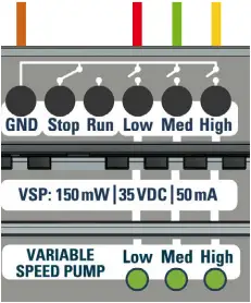
5.2.3 Zodiac FloPro
| Connection table | ||
| Definition analog J3 terminal | Wire color | Connection Smart&Easy Control Module |
| INPUT 1 | Red | Low |
| INPUT 2 | Green | MId |
| INPUT 3 | Yellow | High |
| INPUT 4 | – | – |
| COMMON (5) | Brown | GND |
5.2.4 Pentair Dura I VS2 & Ultraflow VS2
| Connection table | ||
| Definition | Wire color | Connection Smart&Easy Control Module |
| +5V output for digital Inputs | Red | Run |
| Common Ground | Black | – |
| Speed 1 Digital Input | White | High |
| Speed 2 Digital Input | Blue | Low |
| Speed 3 Digital Input | Orange | Med |
| Quick Clean Digital Input | Brown | – |
| RS-485A | Green | – |
| RS-485A | Yellow | – |
► Hint
The colour coding of all cables is specified by the pump manufacturer. Make sure that the color assignment given here matches the one in the pump data sheet!
5.3 Pool heating
The following connection variants are supported by the Smart&Easy Control Module. To choose the right type of wiring, please consult the instructions for your heating system.
A) Direct control of the heating system
Controls the heating directly. Depending on the model, there is a separate input (terminal) dedicated to the remote control of the heat pump, where the switching cable from the Smart&Easy Control Module can be connected.
(1) Electric Heater / Heat Pump
(2) Internal flow switch of the heater
(3) Connection to OUT 1 – 4
B) Control via the flowswitch input
In this case, the Smart&Easy Control Module is connected in series with the flow switch, see connection diagram.
(1) Electric Heater / Heat Pump
(2) Internal flow switch of the heater
(3) Connection to OUT 1 – 4
► Hint
Attention: Many heat pumps have a dedicated terminal that allows the filter pump to be controlled by the heat pump. This terminal is usually located next to the heat pump’s power terminal. The Smart&Easy Control Module must not be connected to this terminal block.
5.4 Pool Lighting (Underwater Light)
When installing a 12 V pool lighting, a transformer is required, which can be installed according to the following figure.

a) 230V AC + RCS (≤ 30 mA)
(1) Circuit breaker
(2) Transformer for pool lighting
(3) Pool Lighting
(4) OUT 1 – 4
► Hint
– The transformer must be designed according to the pool lighting to be connected.
– A 230 V AC control, e.g. for ambient lighting, is shown in point 5.5.
5.5. Other (pool) equipment
In addition to the installations already mentioned, you have the option of using the Smart&Easy Control Module to switch other 230 V-operated devices, such as the outdoor lighting. This function is called the universal switching function and is generally connected as follows:

a) 230V AC + RCD (≤ 30 mA)
(1) Circuit breaker
(2) Device / Other (pool) equipment
(3) OUT 1 – 4
► Hint
For the switching large electrical loads, such as pumps or fans, a power contactor must be used to separate the control and main circuits. (analogous to point 5.1. Single-stage filter pump)
6 Initial commissioning and pairing with the Automatic device
1) Make sure your Automatic has the latest software installed. An update is carried out via USB stick (see the operating instructions of your Automatic). The latest version can be found on our Bayrol Technik support page: https://www.bayrol.de/bayrol-technik-support
2) As soon as the Smart&Easy Control Module-Icon ![]() appears in the menu bar of your Automatic, the Smart&Easy Control Module can be connected.
appears in the menu bar of your Automatic, the Smart&Easy Control Module can be connected.
- Click on the icon.
- Select “Connect to Smart&Easy Module or Box” and follow the step-by-step instructions.
Your Automatic device may ask for another software update after connecting the Smart&Easy Control Module. This may be necessary to update also the connected Smart&Easy Control Module to the latest software version. To access the “Functions” menu, touch the home screen switching icon in the upper left corner.
3) Note: The following statuses are indicated by different icons:
 → No Smart&Easy Control Module connected to the Automatic yet.
 → An existing connection to a Smart&Easy Control Module has been interrupted. All functions of the Smart&Easy Control Module will be switched off to ensure safety.
 → Connection to the Smart&Easy Control Module is active.
7 Service

(1) Smart&Easy Control Module icon
(2) Function Menu
1) Smart&Easy Control Module icon: contains all the settings needed to use and operate the Smart&Easy Control Module. Depending on the connection status, further step-by-step instructions are offered, which facilitate the initial commissioning and provide helpful tips in case of problems.
2) In the “Functions” menu, as shown in the figure, the following information is displayed:
– Display of all selected and integrated functions and their additional properties.
– Clicking on one of the functions will take you to the respective submenu.
– Display of all important measurement parameters in the lower row
8 Function Configuration
Once you have successfully connected your Smart&Easy Control Module, you can use the Smart&Easy Control Module icon to define your connected functions (pool equipment).
→ It is best to use the step-by-step instructions for the initial commissioning.
8.1 Filter Pump
Use the toggle button to select whether you are using a frequency-controlled or single-stage filter pump. When using a VSP, the digital outputs will be used to control 3 different speeds of the pump.
When using a single-speed filter pump (ON/OFF): Please make sure that the use of a VSP via the toggle button is deactivated and please select a free output (OUT 1 – 4) to which the pump should be connected.
Features:
– 3 timers
– Smart-Mode:
Automatic regulation of the filter duration depends on the measured pool temperature. To do this, enter the desired start time, the pump speed (VSP only), and the respective filter duration at 30 °C and at 12 °C. The filter duration is now automatically calculated for the water temperature measured in the pool and no timers are required.
– Winter Mode:
If the water temperature drops below 12°C, the filter pump is only switched on for a defined period. To do this, enter the duration and the desired pump speed (VSP only).
– Anti Freeze Function:
When the antifreeze function is activated, the filter pump is automatically switched on as soon as the water temperature measured in the pool drops below an adjustable value. To do this, enter the desired temperature value, pump speed (VSP only), hysteresis, and minimum runtime.
– Boost Mode:
When the boost mode is activated, the filter pump is automatically activated. This feature is only active on Automatic Salt.
Only possible with VSP:
– Prohibit/allow activation of disinfection and pH dosing for different filter speeds.
– Visual display of the current filter speed in the function menu
– Setting the pump running time with the respective filter speeds in the timers
8.2 Pool lighting multicolor
You have the option of controlling pulse-controlled pool lighting via this function.
Features:
– Definition of pulse duration and on/off switching time
– Toggle button for changing the light program
– 3 timers with the possible definition of the respective light program
► Hint
When using single-color pool lighting, please use the “Universal Switching Function” (point 8.4)
8.3 Heating
This function regulates your heating by activating (AUTO) or deactivating (OFF) the output. In AUTO mode, the heater is turned on until the desired temperature is reached.
► Hint
The function is only active when the filter pump is running. When using a frequency-controlled pump, you can set the pump speed at which the heater can be switched on in the expert menu.
8.4 Universal switching function
In the universal switching function, you have the option of setting up to three timers and only releasing the function when the filter pump is running.
► Hint
If you would like to switch on single-color pool lighting, please use this function.
8.5 Not needed
Please select this setting for switching outputs that are not in use.
9 Declaration
We hereby declare, BAYROL Deutschland GmbH
Robert-Koch-Str. 4
82152 Planegg/Steinkirchen
Germany
that the following product in the versions placed on the market by us complies with the requirements of the EC directives specified below.
Product name: Product Wireless extension module with switching functions for Automatic controllers
type: Smart&Easy Control Module
Serial No.: see type plate on the device
EC Directives: EC Low Voltage Directive (2014/35/EU)
EC Radio Equipment Directive (2014/53/EU)
EC EMC Directive (2014/30/EU)
Harmonised standards applied: EN61000-3-2, EN61000-3-3, EN61000-4-2, EN61000-4-3, EN61000-4-3, EN61000-4-4, EN61000-4-5, EN61000-4-6, EN61000-4-8, EN61000-4-11
Date, Manufacturer’s Signature: 01.03.2024
Signatory details:

Lars Birckenstaedt, Managing Director BAYROL Group
Note! UK CA Declaration of Conformity see page 52.
10 Disposal instructions
![]() Disposal of electrical and electronic household appliances in the European Union
Disposal of electrical and electronic household appliances in the European Union
All products marked with this symbol must not be disposed of with household waste after use. It is the user’s responsibility to dispose of this type of waste by dropping it off at a recycling point suitable for the selective disposal of electrical and electronic waste. The appropriate recycling and treatment of this waste contributes significantly to the preservation of the environment and the health of users. For more information on the collection points for this type of waste, please contact the retailer where you purchased the product or your local council.
11 Safety precautions
Dangers of non-compliance with safety instructions
Failure to comply with the safety instructions can result in a risk to people, the environment and equipment. Failure to comply with the safety instructions will result in the loss of any claim for damages.
![]() Professional installation
Professional installation
This product must be installed by a knowledgeable swimming pool professional. All applicable installation rules and local regulations must also be observed. This product is intended exclusively for use in private swimming pools.
![]() Disconnect supply voltage
Disconnect supply voltage
Hazards can arise as a result of service work with a connected supply voltage, e.g. due to unexpected start-up of the metering pumps.
Possible consequence: property damage or damage to health
– Before all service work, the device must be disconnected from the supply voltage
![]() Opening the chassis
Opening the chassis
If the housing is opened, there is a risk of electric shock.
Possible consequence: Damage to property or health (including danger to life)
– Do not open the device case.
This is especially true if the device is still connected to the power supply.
![]() Dangerous Settings
Dangerous Settings
Improper modification of the system settings can lead to dangerous operating situations under certain circumstances.
Possible consequence: property damage or damage to health
– If necessary, consult a professional.
– In the event of improper application or change of values, liability is transferred to the operator of the system.
![]() Unauthorized access
Unauthorized access
Unauthorized access can lead to dangerous settings.
Possible consequence: property damage or damage to health
– Make sure that unauthorized access to the device is not possible.
![]() Unexpected start-up
Unexpected start-up
The device starts working as soon as voltage is applied to the mains input.
Possible consequence: property damage or damage to health
– Do not supply the device with power until all preparations for safe start-up and operation have been completed.
![]() IMPORTANT NOTE!
IMPORTANT NOTE!
The system operator must ensure compliance with the local accident prevention regulations, the statutory regulations and the generally recognized safety rules!
Documents / Resources
 | BAYROL 191080 Smart Easy Control Module [pdf] Instructions 191080 Smart Easy Control Module, 191080, Smart Easy Control Module, Easy Control Module, Control Module |