![]() ATESS PVCB8HV
ATESS PVCB8HV
PV COMBINER BOX
Intallation & Operation Manual
About this Manual
This chapter introduces the main contents of this manual and target reader, also explains symbols to help users better understand the following contents.
1.1 Forewords
Dear customer, Thank you for choosing ATESS PVCB8HV smart PV combiner box, we sincerely hope that this product can fulfill your needs.
Your suggestion regarding product performance and function is very much appreciated, we’ll keep updating our product to improve product performance.
1.2 Overview
This manual is specifically for ATESS PVCBBHV smart PV combiner box(referred as combiner box in following contents), major contents include:
Safety instruction
Introduces safety precautions when installing and maintaining combiner box.
Product description
Introduces combiner box system structure, components, function and category.
Installation
Introduces installation instruction and cable connection of combiner box
Routine maintenance
Introduces replacement instruction of fuses etc.
Others
Introduces combiner technical parameters, warranty terms and ATESS contacts.
1.3 Target readers
This manual is intended for the combiner box operator, personnel for maintenance and other works.Operator of combiner box should have basic electrical knowledge, familiar with electrical diagram and component characteristics.
1.4 Use of this manual
Before using this product, please read this manual carefully. Keep this manual and other documents in product accessories together to ensure convenience of obtaining for operating personnel Pictures, logos, symbols are property of ATESS. Disclosure by third party without written authorization is prohibited Manual will be continuously updated but inevitably. thephysical appearance may be of slight deviation with actual product. please refer to finishedgood for actual appearance, latest documents can contact with ATESS Email: info@atesspower.com or distribution channels.
1.5 Others
ATESS PVCB8HV belongs to the high-voltage series combiner box, and currently only one 8- input high-voltage combiner box is available for selection. This manual only explains the PVCB8HV combiner box
1.6 Use of symbols
To ensure safety of operating personnel installing this product, and efficient usage of this manual, some information is emphasized by symbols.
The following list shows all symbols probably be used, please read carefully.
 | Means there’s high risk that might cause casualties or injury if not avoided. |
| Means there’s medium risk that might cause casualties or injury if not avoided. |
 | Means there’s possible risk that might cause injury if not avoided. |
| Note: | means there’s potential risk that might cause equipment failure or personal property loss if not avoided. “Note” is extra information or explanation for certain items that helps understand usage of product or solve problem to save time. |
Please pay attention to safety warning label on product as below:
| This sign means there’s high voltage potential inside that can cause electric shock. | |
| This sign means part of product with high unbearable temperature by human body, touching should be avoided to prevent body injury. | |
| This sign mfeans this part of product should be grounded securely to ensure safety of operating personnel. |
Satety Instruction
This chapter describes overall safety instruction during installation of combiner box. Detail instructions regarding each installation and maintenance step please refer to related warning descriptions.
Please read carefully before any operation, personal injury or equipment damage caused by violation of this instruction is not responsibility of ATESS.
| Touching of cable terminals might result in electric shock or fire hazard Do not touch terminals or conductors connect to inverter or PV string. Follow connection and safety instruction. | |
| Possible high voltage potential electric shock: Please follow warning label on product. Please follow safety instruction in this manual and other documents. | |
| Damaged equipment or system failure might cause electric shock Please visually inspect whether there’s damage or other risky status. Check circuit connection and other equipment to ensure safety No operation till safe status is confirmed. | |
| Only electrician or qualified personnel are allowed for operation or cable connection of this product Warning labels should be clear and visible, damaged ones should be replaced immediately All operation and cable connection should be done in accordance with local. guidance. Cable connection during the day should be done with PV array disconnected or cover, else there will be risk of electric shock due to high voltage potential. Only 1 fuse should be changed once, multiple fuse change simultaneously is not allowed to avoid electric shock. | |
| Touching or improper operation of PCB or electric-static sensitive components can damage components, touching of parts other than cable terminals when installing combiner box is not allowed. Please follow electric-static protection guideline by wearing anti-static wrist band. |
| Note: | Please do not open front cover frequently to maintain water proof performance. |
Product Description
This chapter introduces the characteristics, structure and typical application solution of ATESS ATESS PVCB8HV PV combiner boxes.
3.1 System overview
In large volume solar plant, to reduce connection cables between PV string and inverter, improve convenience of maintenance and reliability, usually combiner boxes are used between PV string and inverter.
ATESS PVCB8HV outdoor combiner box is designed especially for large volume solar plant application, it is suitable to be used together with ATESS central inverters in a solar plant solution.
By using combiner box, PV modules are connected in series to form a string and then connect to combiner box, typical connecting diagram is as below: Chart 3-1 component list
| No. | Name |
| A | PV strings |
| B | ATESS PVCB8HV combiner box |
| C | PV inverter |
| D | Data logger |
| E | Environments sensors |
| F | Utility grid |
Features:
- Outdoor applicable.
- Multiple PV string connection, fuse equipped for each input.
- PV specified surge protection device available.
3.2 Packing list
- Combiner box.
- Key for front cover lock.
- Fuse.
- Bracket.
- Installation manual.
Warranty card. - Certification of qualification.
- Final inspection report.
3.3 Mode description
The detail explanation of model name is as below: 3.4 Product label
User can find product information on the label which is stuck on the side panel of enclosure, detail of product label is as below:
Note: Product label contains detail model name, serial number and parameters of each product, serial number is unique for each product, this number is stored in ATESS database, maintenance and other information later on will be stored in this database by serial number, please keep product label for tracing.
3.5 System structure
3.5.1 Product appearance
Different models of ATESS PVCB8HV combiner boxes are similar in appearance, if ATESS PVCB8HV combiner is used, the 8 redundant cable gland on bottom of enclosure be sealed, detail please see below figure.
| No. | Name | Description |
| A | Lock | – |
| B | Input DC+ | Positive input of PV string |
| C | Input DC- | Negative input of PV string |
| D | Grounding cable input | Grounding cable connecting point |
| E | Monitor | – |
| F | Output DC+ | Positive output of combined string |
| G | Output DC- | Negative output of combined string |
| H | Ventilation valve | Water and dust proof valve for ventilation of inner space |
3.5.2 Inner layout
The inner layout of ATESS PVCB8HV is shown in figure 3-4.
| A | SPD |
| B | DC/DC BUCK |
| C | DC breaker |
| D | Control board |
| E | Positive fuses |
| F | RS485 terminal |
| G | Negative fuses |
| H | Grouding terminal |
| J | Switching mode power supplies |
Note: Layout varies for different models, please refer to actual product
3.6 LED operating instruction
The communication parameters can be seen on LEDs on the control board, communication address, operation parameter setting and checking can be realized via 3 push buttons. LED indicator diagram:
01—-Index number
2—-Space
3—-Status
4567—-Parameter value
Function of 3 push buttons are different in different page, details please see below:
Data browsing page:
Key2—Page up
Key3—Page down
Key1—Enter pageword
Password input page:
Key1—Enter
Key2—Left right adjustment of digit
Key3—Digit value change
Note: Push enter button to change password, digit indicator light up means parameter changeable, right password leads to setting page, wrong password leads to browsing page.
Parameter browsing page:
Key1—Enter(Parameter setting page, save setting, back to main page)
Key2—Page up
Key3—Page down
Parameter setting page:
Key1—Enter(Press to confirm modification, digit indicator light up, parameter changeable)
Key2—Left right adjustment of digit
Key3—Digit value change
3.7 Fuse rating
In power system, fuse is used to protect electronic component from overcurrent damage, component might deviate, overheat, damaged or even cause fire hazard.
Proper fuse rating should be chosen according to PV module parameters and related regulations, fuse with too high rating cannot provide protection, fuse with too low rating affect normal operation.
Lower limit of fuse rating should be calculated from short circuit current of PV module.It is recommended to use 1.56 Isc if there’s no special requirement by local regulation.according to above method, user can calculate fuse rating according to PV module parameters. For example, Isc of PV module is 20A, then fuse current rating is recommended to be 20A x 1.5~30A, voltage range of PV array is 0-1500V, so rating of fuse is 1500V/30A.
3.8 DC circuit breaker rating
Maximum PV array voltage is 1500V, so rating of DC breaker in combiner box should not be lower than 1500V, ATESS combiner box uses 2 pole breaker, the breaker can withstand 1500V high voltage to meet solar plant requirement.
3.9 SPD specification
| Item | Parameter |
| -Ucav | 1.5kV (V+ ∼ V-,V+ ∼ PE,V- ∼ PE) |
| -In | 20kA(8/20 us) |
| -Imax | 40kA(8/20 us) |
| -UP(\IN) | 3.8kV (V+ ∼ V-,V+ ∼ PE,V- ∼ PE) |
| Terminal cable size | 1.5mm² 2 ∼ 25mm² ( flexible cable)/ 35mm² non-flexible cable |
| Warning signal interface rated current | 125 Vac & 1 A(Max), 5 V& 0.5 mA(Min) |
| Enclosure flame retardant level | UL94V-0 |
| Protection level | IP20 |
3.10 Spare parts
- Fuse
- Fuse holder
Installation
This chapter introduces environment requirement and installation instruction of combiner box.
4.1 Per-installation inspection
Check according to packing list in chapter 3.2 that all accessories included.
All shipped goods have been fully inspected at factory, but consider possible damage during transportation, a full inspection is recommended before installation.Any damage please contact logistic company or ATESS directly.
4.2 Install tools
Electric drill, wrench, cross screw driver, socket, expansion bolt, fixing angle steel.
4.3 Mechanical installation
4.3.1 Dimensions
Different models are same in dimension and appearance, different in terminal quantity (marked in dot line). Dimension of combiner box is 600mmX500mmX187mm(WxHxD) as shown in below figure, installing hole distance:660mmX400mm(WXH). 4.3.2 Environment requirement
ATESS PVCB8HV combiner box has IP65 protection level, suitable for outdoor application, please follow below requirement when choosing installing environment:
- Keep enough space according to combiner box dimension.
- Environment temperature should be between -25°C~55°C, relative humidity 0~99%.
- Install combiner box close to PV modules to reduce cable length.
- Environment should be dry and with good ventilation, dust proof.
- Install upside down is prohibited, recommend to install on wall or pole vertically.
– wall mount: recommend to use bolt to fix combiner box to the wall through the installation hole on each side.
– pole mount: recommend to use hoop and angel steep as supporting bracket, fix combiner box to the pole with bolt - Avoid direct sunshine, this might cause overheat which can affect power yield of system, and service life of combiner box as well.
- In large volume plant, recommend to install combiner box on the PV module bracket which is shaded by PV module.
- Keep space surrounding combiner box for installation, maintenance and better heat dissipation.
Note: Humid environment can damage combiner box, avoid installation during rain or high humidity.
Note: Redundant terminal should be sealed in case combiner box installed horizontally. Water proof gland should always be securely tightened to ensure waterproof performance..
4.3.3 Installing instruction
When installed on PV module bracket, hex-bolt (M10*40), flat washer (Φ10), spring washer( Φ 10)are needed.
User can also choose bolt according to installing condition
- Installing hole on PV module bracket should be in accordance with dimension shown in below figure

- Fix combiner box to bracket firmly with bolt and nut in sequence shown in below, from left to right are bolt, ear on box, bracket, flat washer, spring washer, nut. Torque 45Nm

- Check whether combiner box is securely fixed
Combiner box can also be installed on other metal brackets, for instance, on rooftop system, it can be fixed to metal brackets in the shaded area, installation should be done according to instruction in this manual and local regulations.
4.4 Electrical installation
4.4.1 Overview
ATESS PVCB8HV can connect maximum 8 strings, if actual string quantity is less than 8, redundant cable glands should be sealed with water proof cap.
Each string is equipped with PV specified fuse for system protection, voltage of PV string should be tested before inserting fuse to make sure it’s within 1500V and all strings are grounded properly.
4.4.2 Cable and glands
Water proof cable glands are equipped for input, output, communication, power and grounding cables, all located on the bottom of combiner box, cable size should be in accordance with specification of related glands shown in below figure: Cable size list
| Terminal Location | Terminal Spec | Recommended Cable Size |
| DC positive input | PG9 | 6mm² |
| DC negative input | PG9 | 6mm² |
| DC positive output | Pg25 | 70mm² |
| DC negative output | PG25 | 70mm² |
| Grounding | PG11-10G | 16mm² |
| Communicatioy | PG16-14G | 1.5mm² low resistance quad-core twisted pair |
Note: Recommended cable size is common cable specification, it might vary for different suppliers, also different size cable can be used for different PV module type, it should be above the lower limit of waterproof cable gland.
4.4.3 Preparation before cable connection
Step 1, Open front cover
All combiner boxes are equipped with a specific key, to open front cover, inse figure and turn anti-clockwise; to close, turn clockwise. Step 2, Put breaker in off position.
 Step 3, Open all fuses. Skip this step if fuses are not pre-installed in factory.
 4.4.4 Input cable connection
| There’s high voltage potential on PV string that might cause fatal electric shock or serious injury, please follow below instruction when connecting PV input cables: • Cover PV modules with light-proof materials. • Follow safety regulation per PV module supplier. | |
| Incorrect cable connection might cause damage to combiner box, inverter and PV module, please follow below instruction: • Connect cable according to drawing.. • Check string voltage within combiner box rating. • Confirm negative, positive pole and grounding. |
Step 1 Take off waterproof cap of cable glands on bottom of combiner box.
Step 2 Put cable marked PV1+ through cable gland in bottom area marked with Input DC+, and then connect to PV1+ terminal, keep redundant cable length for fixing and bending.
Step 3 Peel protecting and insulation layer of cable, keep a 10mm length bare copper core. Step 4 loosen the fixing screw of terminal, insert copper core of cable to terminal, then tighten screw as figure 4-6.
 Step 5 connect rest of cables to terminals in the same way. Then combine all cables and tie to fixing bar with cable tie.
 4.4.5 Output cable connection
Step 1 Take off waterproof cap on output cable glands…
Step 2 Put cable marked with DC through DC output(+) glands, put cable marked with DC- through DC output, keep proper redundant length.
Step 3 Peel protecting and insulation layer of cable, keep a 25mm length bare copper core,
Step 4 Lock positive cable to positive terminal, negative cable to negative terminal.
Step 5 Put waterproof cap back and tighten by turning clockwise.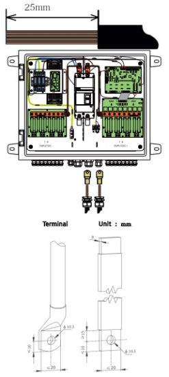 Wiring precautions:
- First remove the PG head of the M32, pass the stripped 70mm² cable through the PG head, and then press the terminal on the cable with a tool. Install the PG head, and then connect the wire to the switch, last tighten the PG head after finishing the wirining.
- Pay attention to the size of the wiring terminais, as shown in the schematic above
![]() Make sure fixing screw of terminal securely tightened, insufficient contact between cable copper core and terminal might cause overheat and even damage, multicore cable is recommended with size not lower than specified value.
Make sure fixing screw of terminal securely tightened, insufficient contact between cable copper core and terminal might cause overheat and even damage, multicore cable is recommended with size not lower than specified value.
Waterproof cap should be exactly in position to avoid water going in to damage combiner box.
4.4.6 Grounding connection
Grounding cable should be properly connected or else it:
- Might cause fatal electric shock at failure.
- Might cause combiner box damage by lightning surge.
Note: Please follow related regulation to:
- Connect grounding cable securely.
- Test grounding resistance to make sure it’s within 10 ohm.
Step 1 Loosen waterproof cap of GND cable gland.
Step 2 Put yellow/green cable through gland, keep redundant length.
Step 3 Peel protecting layer and insulation layer of cable, keep bare copper core around 15mm.
Step 4 Loosen GND terminal screw with flathead screwdriver.
Step 5 Insert copper core of cable in terminal, then tighten cable terminal with screw and tie cable to fixing bar, keep redundant cable length.
Step 6 Turn waterproof cap clockwise to fix it back to gland.
4.4.7 Fuse installation
Use wire nipper to put fuse into fuse holder, close fuse holder firmly to avoid insufficient contact. Fuse model SLPV-30 with 30A/1500V rating is recommended, if the fuse is damaged, user can purchase locally or from ATESS. Note: Fuse must be completely pulled out of fuse holder to avoid injury or equipment damage during installation or replacement,
4.4.8 Bottom cable layout
Cable layout on bottom of combiner box is shown in figure 4-8: Note: After finishing installation or maintenance, front cover must be locked firmly, water cap of lock should be covered securely to avoid component damage caused by water. ATESS is not responsible for such damage without following instruction.
4.5 Start and stop combiner box
Combiner box start and stop automatically when powered on and off, the DC output can be disconnected by switching off inner DC breaker.
Routine Maintenance
This chapter describes routine maintenance work and period.
5.1 Notice on maintenance
Components in the combiner box age and breakdown due to environment temperature, humidity, dust and vibration, this can cause possible failure, thus routine maintenance should be done periodically.![]() Only certified electrician is qualified for maintenance work in this chapter..
Only certified electrician is qualified for maintenance work in this chapter..
Note: Do not leave metal parts like screw, washer in the combiner box which probably will damage the equipment.
Combiner box should be stopped before maintenance to make sure contact part is not live,
5.2 Replace fuse
Blown fuse is not recoverable, it should be replaced by qualified operator in time.![]() There’s high voltage potential on fuse, touching fuse in operation is prohibited.
There’s high voltage potential on fuse, touching fuse in operation is prohibited.
DC breaker must be disconnected before replacing fuse, also it should be confirmed with a current meter that string current is 0 to avoid high voltage risk. after that the fuse can be taken off for PV module or combiner box maintenance.![]() Fuse with same rating must be used for replacement
Fuse with same rating must be used for replacement
Make sure fuse holder is securely clamped
5.3 SPD maintenance
SPD should be checked periodically, status of SPD is visible at monitoring center, confirmation and replacement should be done immediately when abnormal detected.
Appendix
Technical specification, warranty, disclaimer and contact details of ATESS are included in this chapter.
6.1 Technical specification
6.1.1 Parameters
| Model | ATESS PVCB8HV |
| Max number of string | 8 |
| Max input current | 20A |
| Input voltage range | 300Vdc~1500Vdc |
| Protection level | IP65 |
| Environment temperature | -25°C~4+55°C |
| Humdity | 0~99% |
| Weight | 24kg |
| Dimension(L*W*H) | 600mm*500mm*187mm |
| Install hole distance | 660mm*400mm |
6.1.2 Cable specification
| Model | ATESS PVCBBHV |
| Input cable | Cross section:4-6mm² multi-core flame retardant copper cable |
| Peeled Length:10mm | |
| Screw: M4 | |
| Torque:1.2N.m | |
| Output cable | Cross section:70mm² |
| Peeled length:25mm | |
| Screw: M8 | |
| Torque:23N.m(±10%)N.m | |
| Grounding cable | Cross section:16mm² multi-core flame retardant copper cable |
| Peeled Length:15mm | |
| Screw: M6 | |
| Torque:3N.m |
6.2 Warranty
ATESS is responsible for replacing or repair of product within warranty periods.
Warranty claim documents
User should provide receipt, purchasing date to ATESS for warranty claim, also the brand label should be clear, else claim might be rejected.
Terms and conditions
- Replaced failed units will be disposed by ATESS.
- User should leave reasonable time to ATESS to repair failed units.
Disclaimer
- ATESS has the right to reject warranty claim for below conditions:
- Whole unit, components are out of warranty period.
- Damage during transportation.
- Incorrect installation, modification or application.
- Extreme environment operation out of rated specification.
- Ailure or damage caused by installation, repair or modification by personnel from agents other than ATESS.
- Failure or damage caused by using components or software from agents other than ATESS.
- Installation or application without following international standards
- Failures caused by above conditions, ATESS service department can evaluate the situation and repair and charge user a reasonable amount of money.
Note: Dimension and parameter may be changed without notification, please refer to latest document for most updated data.
6.3 About ATESS
Company Name: Shenzhen ATESS Power Technology Co.,Ltd
Address: 2nd Floor of Building 23, Zhulongtian Road, Shuitian Community, Shiyan Street, Baoan District, Shenzhen
Service line.
Tel: +86 755-29988492
Fax: +86 755-29985623
E-mail: info@atesspower.com
Web: www.atesspower.com
![]()
 SHENZHEN ATESS POWER TECHNOLOGY CO.,LTD
GROWATT-ATESS Industrial Park, No.23 Zhulongtian Road, Shuitian Community.
Shiyan Street, Baoan District, Shenzhen
Tel: +86 755 2998 8492
Email: info@atesspower.com
Website: www.atesspower.com
Revised date: 2024-09-20
Documents / Resources
 | ATESS PVCB8HV Pv Combiner Box [pdf] Instruction Manual PVCB8HV Pv Combiner Box, PVCB8HV, Pv Combiner Box, Combiner Box, Box |