
1. Product Overview
The ALIENTEK DM40C is a versatile 3-in-1 handheld device combining a high-performance 4.5-digit true-RMS multimeter, a 10MHz bandwidth digital oscilloscope, and a programmable signal generator. This compact tool is designed for various applications, including automotive electronics, embedded development, and general circuit analysis, providing precise measurements and signal visualization capabilities.
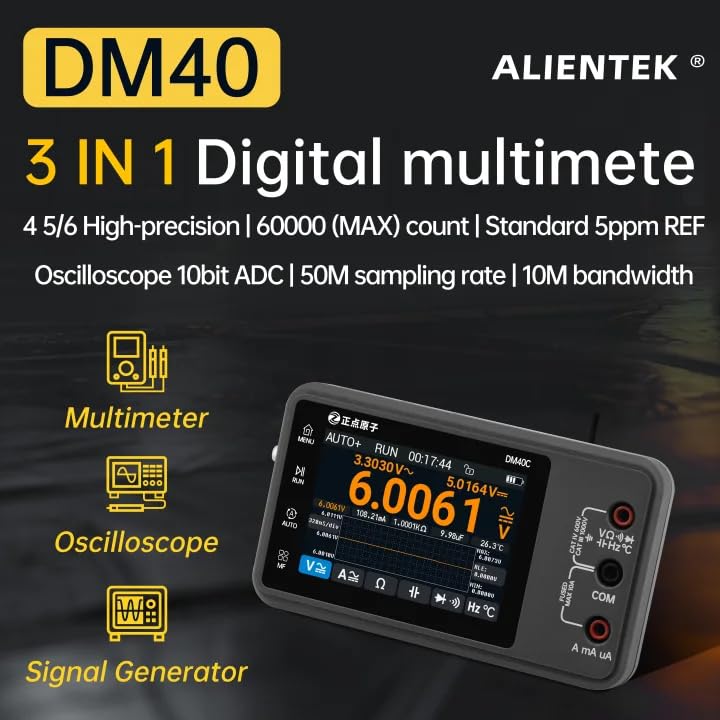
Figure 1: ALIENTEK DM40C Digital Multimeter, showcasing its 3-in-1 functionality as a multimeter, oscilloscope, and signal generator.
Key features include 4.5-digit accuracy with 60,000 counts, True RMS measurement for AC/AC+DC readings, a 50MSa/s oscilloscope with 10MHz bandwidth, and a signal generator capable of producing various waveforms up to 10MHz. The device features a 3.5-inch IPS capacitive touchscreen for intuitive operation and offers over 10 hours of battery life with USB-C charging.
2. Package Contents
Verify that all items listed below are present in your package:
- DM40C Multimeter Host (including bracket and ordinary PVC sleeve)
- MP02 High-quality Multimeter Probes (one pair)
- Adjustable MCX Oscilloscope Probe Cable
- MCX Crocodile Clamp Probe Wire
- USB Type-C Cable (1.2m)
- WRN-01C Thermocouple Temperature Probe (Note: Availability may vary by version. If not included, temperature measurement functionality requires a compatible probe.)

Figure 2: Contents of the ALIENTEK DM40C package, including the multimeter, various probes, and charging cable.
3. Setup
3.1 Initial Charging
Before first use, fully charge the DM40C using the provided USB Type-C cable and a compatible USB power adapter. The device has a built-in rechargeable battery providing over 10 hours of operation.
3.2 Installing the Silicone Case
To protect your DM40C, install the silicone protective case:
- Take the multimeter and the silicone case.
- Align the power button hole on the silicone case with the multimeter's power key.
- Gently slide the multimeter into the silicone case until it is fully seated.

Figure 3: Step-by-step guide for installing the silicone protective case onto the DM40C multimeter.
The silicone case also includes a kickstand for convenient bench use and a magnetic back for attaching the meter to metal surfaces.
3.3 Connecting Test Leads
The DM40C features a 3-jack design. Connect the test leads according to the measurement function you intend to use. The device is designed to minimize connection errors with its innovative design.
4. Operating Instructions
The DM40C features a 3.5-inch IPS capacitive touchscreen for navigation and control. The user interface is designed for intuitive operation.
4.1 Multimeter Functions
The DM40C provides professional-grade precision for various electrical measurements.
- Automatic Measurement: The device supports auto mV/V gear measure (DC: 0.01mV~1000V, AC: 0.01mV~750V) and auto uA/mA/A gear measure (0.01uA~10A). This eliminates the need to manually switch modes and sockets for most measurements.
- True RMS (TRMS): For accurate AC/AC+DC readings, even with distorted waveforms.
- Diode and Continuity Test: Features a 4-stage voltage drop measure for diodes and quick continuity testing (less than 1µs).
- Trend Chart: Displays measurement data periodically with a 3-speed adjustable time base (160ms/320ms/640ms).

Figure 4: The automatic measurement screen of the DM40C, showing one-click auto measurement for voltage and current.

Figure 5: Display showing T-RMS measurement and a trend chart for visualizing signal changes over time.

Figure 6: Screen illustrating the multi-functional diode and continuity measurement capabilities.
4.2 Oscilloscope Function
The built-in oscilloscope allows for signal visualization and analysis:
- Specifications: 50MSa/s sample rate, 10MHz bandwidth, 10-bit ADC, 64Kpts memory.
- Waveform Visualization: Observe waveform rise times, ringing, and noise in real-time.
- FFT Analysis: Pinpoint harmonic issues in power supplies, logic signals, or sensor outputs.
4.3 Signal Generator Function
The programmable signal generator can produce various waveforms for testing circuits:
- Waveform Types: Sine, square, triangle, and sawtooth waveforms.
- Frequency Range: Up to 10MHz for certain wave types.
- Output Amplitude: Up to 3.0Vpp.
This function allows for injecting test signals and observing the circuit's response directly on the DM40C's oscilloscope, facilitating closed-loop testing.
4.4 General Operation Tips
- Touchscreen Interface: Navigate menus and adjust settings using the 3.5-inch IPS capacitive touchscreen.
- One-Key AUTO Range: Utilize the auto-ranging feature for quick and convenient measurements.
- Auto+ Mode: For voltage measurements, consider using the "Auto+" mode to prevent the meter from starting in the mV range, which can cause this behavior when measuring larger voltages. This mode ensures the meter starts in the V range.
Video 1: Demonstration of the DM40 Digital Oscilloscope Multimeter's voltage measurement function, including the "Auto+" mode to skip the mV range.
5. Maintenance
5.1 Cleaning
Wipe the device with a soft, dry cloth. Do not use abrasive cleaners or solvents. Ensure the device is powered off and disconnected from any power source before cleaning.
5.2 Battery Care
The DM40C uses a rechargeable battery. For optimal battery life, avoid fully discharging the battery frequently. Recharge the device using the provided USB Type-C cable. If the device will not be used for an extended period, charge it to approximately 50% before storage and recharge every few months.
5.3 Firmware Updates
ALIENTEK periodically releases firmware updates to add features and fix bugs. Connect the DM40C to a PC via the USB-C cable for data logging and firmware updates. Refer to the official ALIENTEK website for the latest firmware and update instructions.
6. Troubleshooting
- Device not powering on: Ensure the battery is charged. Connect the USB-C cable to a power source and attempt to power on.
- Inaccurate readings: Verify test lead connections are secure and correctly inserted for the selected function. Ensure the correct measurement mode is selected. For critical measurements, consider field calibration if available or compare with a known reference.
- Oscilloscope signal noise: Check probe connections and ensure proper grounding. External interference can affect oscilloscope readings.
- "OL" (Overload) display: This indicates the measured value exceeds the current range. In automatic measurement modes, the device should typically adjust. If "OL" persists, ensure the input is within the device's maximum specifications.
- Repeated relay switching during voltage measurement: Use the "Auto+" mode to prevent the meter from starting in the mV range, which can cause this behavior when measuring larger voltages.
7. Specifications
The following table details the technical specifications for the ALIENTEK DM40C Digital Multimeter:
| Feature | Specification |
|---|---|
| Model | DM40C Deluxe Version |
| Display | 3.5-inch IPS Capacitive Touchscreen (480x320) |
| Counts | 59999 (4.5-Digit) |
| DC Voltage Range | 0.01mV to 1000V (Auto Measure) |
| AC Voltage Range | 0.01mV to 750V (Auto Measure) |
| DC Current Range | 0.01uA to 10A (Auto Measure) |
| AC Current Range | 0.01uA to 10A (Auto Measure) |
| Resistance Range | Up to 60MΩ |
| Capacitance Range | Up to 60mF |
| Frequency Range | 10Hz - 60MHz (Multimeter), 1Hz - 10MHz (Signal Generator) |
| Oscilloscope Sample Rate | 50MSa/s |
| Oscilloscope Bandwidth | 10MHz |
| Oscilloscope Memory Depth | 64Kpts |
| Signal Generator Waveforms | Sine, Square, Triangle, Sawtooth |
| Signal Generator Output (Vpp) | 0.5V-3.0Vpp (Square wave up to 3.0Vpp) |
| Battery Life | >10 hours (Multimeter), >10 hours (Oscilloscope) |
| Dimensions | 142 x 83 x 28mm (5.59 x 3.27 x 1.1 inches) |
| Weight | 260g (0.57 lbs) |
| Interface | USB Type-C, MCX, Banana Seat |
| Safety Certification | CE, FCC |
Note: Specifications are subject to change without prior notice.
8. Warranty and Support
ALIENTEK provides ongoing support for its products, including firmware updates and technical assistance. For specific warranty details, please refer to the documentation included with your purchase or visit the official ALIENTEK website. For technical inquiries or support, please contact ALIENTEK customer service.


