
1. Introduction
This instruction manual provides comprehensive guidance for the installation, operation, maintenance, and troubleshooting of the WUTIMK 650-044 (12V) and 650-045 (24V) Speed Governor Control Units. These modules are designed to serve as generator interface controllers, ensuring stable and precise speed regulation for various generator applications. Please read this manual thoroughly before attempting any installation or operation.
2. Safety Information
WARNING: Improper installation or operation can lead to serious injury or equipment damage. Always follow safety precautions.
- Ensure all power sources are disconnected before installation or maintenance.
- Only qualified personnel should perform installation and wiring.
- Verify correct voltage (12V for 650-044, 24V for 650-045) before connecting the module.
- Avoid contact with live electrical components.
- Protect the module from moisture, dust, and extreme temperatures.
3. Product Overview
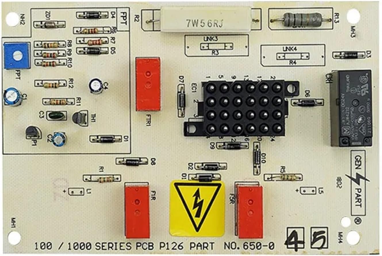
The WUTIMK 650-044/650-045 is a Printed Circuit Board (PCB) based control unit designed for generator speed governing. It integrates various electronic components to monitor and adjust engine speed, maintaining optimal performance.
3.1 Components
The control unit consists of a main PCB with several key components:
- Input/Output Connector: For connecting to the generator's wiring harness.
- Voltage Regulators: To ensure stable power supply to internal circuits.
- Control Circuitry: Microcontrollers and analog components for speed sensing and adjustment.
- Relays/Actuators: For controlling external devices related to speed regulation.
- Adjustment Potentiometers: For fine-tuning speed settings (if applicable).
3.2 Product Images

4. Setup and Installation
Careful installation is crucial for the proper functioning of the speed governor control unit.
4.1 Mounting
- Select a secure, vibration-free location near the generator's engine.
- Ensure the mounting surface is clean and dry.
- Use appropriate fasteners to secure the PCB, utilizing the mounting holes provided on the board. Avoid over-tightening.
4.2 Wiring Connections
Refer to your generator's specific wiring diagram for detailed connection points. The following outlines general connections:
- Power Input: Connect the appropriate DC voltage (12V for 650-044, 24V for 650-045) to the designated power terminals. Observe polarity.
- Speed Sensor Input: Connect the generator's magnetic pickup or speed sensor output to the speed input terminals.
- Actuator Output: Connect the control unit's output to the generator's fuel or throttle actuator.
- Ground: Ensure a solid ground connection to the generator chassis.
CAUTION: Double-check all wiring connections for correctness and security before applying power. Incorrect wiring can damage the module or other generator components.
5. Operating Instructions
Once installed and wired correctly, the speed governor control unit will automatically regulate the generator's engine speed.
5.1 Initial Startup
- Ensure all safety checks are complete.
- Start the generator according to its manufacturer's instructions.
- Observe the engine speed. The control unit should automatically adjust the actuator to reach and maintain the target operating speed.
5.2 Speed Adjustment (if applicable)
Some models may feature onboard potentiometers for fine-tuning the target speed or gain settings. If present, use a small, non-conductive screwdriver to make minor adjustments. Turn clockwise to increase speed/gain, counter-clockwise to decrease. Make small adjustments and observe the effect before further changes.
6. Maintenance
The WUTIMK Speed Governor Control Unit is designed for reliable operation with minimal maintenance. However, periodic checks are recommended.
- Visual Inspection: Annually inspect the module for any signs of physical damage, corrosion, or loose connections.
- Cleaning: If necessary, gently clean the PCB with a soft, dry brush or compressed air to remove dust and debris. Do not use liquid cleaners.
- Connection Check: Periodically verify that all wiring connections are secure and free from wear.
WARNING: Disconnect all power before performing any maintenance.
7. Troubleshooting
If the generator experiences speed control issues, consult the following troubleshooting guide:
| Problem | Possible Cause | Solution |
|---|---|---|
| Engine speed unstable/hunting | Incorrect gain setting; faulty speed sensor; loose wiring. | Adjust gain potentiometer (if available); check speed sensor and its wiring; verify all connections. |
| Engine does not reach target speed | Incorrect speed setting; actuator malfunction; insufficient power to module. | Adjust speed potentiometer (if available); check actuator operation; verify power supply voltage (12V/24V). |
| Module not powering on | No power supply; incorrect voltage; reversed polarity; blown fuse (external). | Check power input connections; confirm correct voltage and polarity; inspect external fuses. |
| No response from actuator | Faulty actuator; broken wiring to actuator; module output failure. | Test actuator independently; check actuator wiring; consult support if module output is suspected. |
If issues persist after following these steps, contact technical support.
8. Specifications
| Parameter | WUTIMK 650-044 | WUTIMK 650-045 |
|---|---|---|
| Input Voltage | 12V DC | 24V DC |
| Product Name | Speed Governor Control Unit / Generator Interface Controller Module | |
| Dimensions (Approx.) | 16 cm x 12.5 cm x 8 cm (L x W x H) | |
| Application | Generator Speed Control | |
| Package List | 1 * Controller Module | |
9. Warranty and Support
9.1 Warranty Information
WUTIMK products are manufactured to high-quality standards. This product is covered by a standard manufacturer's warranty against defects in materials and workmanship. The warranty period typically begins from the date of purchase. Please retain your proof of purchase for warranty claims. This warranty does not cover damage caused by improper installation, misuse, unauthorized modifications, or external factors such as power surges or environmental damage.
9.2 Technical Support
For technical assistance, troubleshooting beyond this manual, or warranty inquiries, please contact WUTIMK customer support through the retailer where the product was purchased or visit the official WUTIMK website for contact information.


