1. Introduction
This manual provides essential information for the safe and efficient operation of your Generic AT5-1500X 1500W Inverter Speed Governor. This device is designed for precise motor speed adjustment, offering robust performance and multiple protection features. Please read this manual thoroughly before installation and use to ensure proper functionality and safety.
2. Safety Precautions
▲ WARNING: Failure to follow these safety precautions may result in death, severe injury, or serious property loss.
- Read the manual carefully before connecting or using the power supply.
- Do not connect the U/V/W output terminals to an AC power supply. Doing so can cause fire hazards.
- The ground terminal of the inverter must be properly grounded.
- Do not install or operate the inverter in environments with explosive gases to prevent explosion risks.
- Only qualified professionals should perform wiring. The inverter contains high voltage internally; do not open the casing without proper authorization and safety measures.

Image: Safety precautions label on the Generic AT5-1500X Inverter.
3. Product Overview
The Generic AT5-1500X is a high-performance inverter designed for precise motor speed control. Key features include:
- Powerful 1500W Output: Delivers 1500W for efficient motor control.
- Input/Output Compatibility: Supports single-phase 110VAC input and 3-phase 220VAC output.
- Comprehensive Protection: Features protection against overcurrent, over/undervoltage, module failure, overheating, short circuit, input/output phase loss, and abnormal motor parameters.
- Digital Display: Integrated digital display for monitoring and adjustment.
- Reliable Performance: Ensures stable operation with electronic thermal relay capabilities.

Image: Front view showing the control panel and rear view showing the heatsink of the AT5-1500X Inverter.
4. Setup and Installation
Follow these steps for proper installation of your inverter:
- Compatibility Check: Ensure your motor is a 3-phase 220V motor. This inverter is designed for such applications.
- Mounting: Securely mount the inverter in a well-ventilated area, away from direct sunlight, excessive dust, moisture, and corrosive substances. Ensure adequate space for heat dissipation.
- Power Input: Connect the single-phase 110VAC power supply to the designated input terminals. Refer to the wiring diagram (if provided separately or on the unit) for correct polarity.
- Motor Output: Connect the 3-phase 220VAC output terminals (U, V, W) to your 3-phase motor.
- Grounding: Connect the inverter's ground terminal to a reliable earth ground. This is critical for safety and proper operation.
- Initial Check: Before powering on, double-check all connections to ensure they are secure and correctly wired.

Image: Internal view of the AT5-1500X Inverter, showing potential wiring terminals. Professional installation is recommended.
5. Operating Instructions
The inverter features a digital display and control buttons for easy operation.
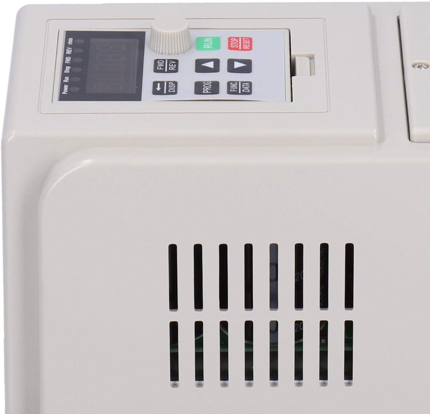
Image: Close-up of the AT5-1500X Inverter control panel.
Control Panel Functions:
- Digital Display: Shows current operating parameters such as frequency, speed, or output voltage.
- RUN Button (Green): Initiates motor operation.
- STOP/RESET Button (Red): Stops motor operation and can reset error conditions.
- FWD/REV Button: Toggles the motor's rotation direction (Forward/Reverse).
- DISP Button: Cycles through different display parameters.
- PROG Button: Enters programming mode to adjust advanced settings.
- FUNC/DATA Button: Used in conjunction with PROG for function selection and data entry.
- Up/Down Arrows (▲/▼): Adjust parameter values or navigate menus.
- Rotary Knob: Primarily used for fine-tuning motor speed or frequency.
Basic Operation:
- Power On: Ensure all connections are correct, then apply power to the inverter. The digital display will illuminate.
- Set Speed: Use the rotary knob to set the desired motor speed or frequency. The display will show the current setting.
- Start Motor: Press the RUN button to start the motor.
- Change Direction: If needed, press the FWD/REV button to change the motor's rotation direction.
- Stop Motor: Press the STOP/RESET button to stop the motor.
- Parameter Adjustment: For advanced settings, press the PROG button to enter programming mode. Use the arrow keys and FUNC/DATA button to navigate and modify parameters. Refer to the detailed programming guide (if available) for specific parameter definitions.
6. Maintenance
Regular maintenance ensures the longevity and reliable performance of your inverter.
- Cleaning: Periodically clean the exterior of the inverter with a soft, dry cloth. Do not use liquid cleaners or solvents. Ensure ventilation openings are free from dust and debris.
- Ventilation: Ensure the installation environment provides adequate airflow to prevent overheating. Check that the cooling fins and fan (if present) are not obstructed.
- Connection Checks: Regularly inspect all wiring connections for tightness and signs of wear or corrosion. Loose connections can lead to poor performance or safety hazards.
- Environmental Conditions: Operate the inverter within its specified environmental conditions (temperature, humidity) to prevent damage.
7. Troubleshooting
If you encounter issues with your inverter, refer to the following common troubleshooting steps:
- No Power/Display Off:
- Check the main power supply and circuit breaker.
- Verify all input power connections are secure.
- Motor Not Running:
- Ensure the RUN button has been pressed.
- Check motor connections (U, V, W) for proper wiring.
- Verify the motor is compatible (3-phase 220V).
- Check for any error codes on the digital display and consult the programming guide for their meaning.
- Overcurrent/Overvoltage/Undervoltage Error:
- Check the load on the motor; it might be too high.
- Verify the input voltage is stable and within the specified range (110VAC).
- Ensure proper grounding.
- Overheating Error:
- Check for obstructions around the inverter's ventilation openings.
- Ensure the ambient temperature is within the operating limits.
- Reduce the motor load if possible.
- Abnormal Motor Noise:
- Check motor parameters in programming mode.
- Ensure motor is properly mounted and balanced.
If the problem persists after attempting these steps, contact qualified service personnel.
8. Specifications
| Specification | Value |
|---|---|
| Item Type | Inverter |
| Material | Plastic |
| Model | AT5-1500X (Genericnov3lzwm61) |
| Power Output | 1500W |
| Power Phase Number | Single phase input, 3-phase output |
| Input Voltage | Single-phase 110VAC 50/60Hz |
| Output Voltage | 3-phase 220VAC |
| Protection Modes | Overcurrent, overvoltage, undervoltage, module failure, overheating, short circuit, input/output phase loss, abnormal motor parameter adjustment, electronic thermal relay |
| Parcel Dimensions | 21 x 20 x 17 cm |
| Item Weight | 1.29 kg |
| Country of Origin | China |
9. Warranty Information
This product comes with a manufacturer warranty for 90 days from the date of purchase. Please retain your proof of purchase for warranty claims. The warranty covers defects in materials and workmanship under normal use. It does not cover damage caused by improper installation, misuse, accidents, unauthorized modifications, or natural disasters.
10. Contact and Support
For technical support, warranty claims, or further inquiries, please contact your retailer or the manufacturer's customer service department. Refer to your purchase documentation for specific contact details.


