1. Introduction
Welcome to the Klanata ET8202 Digital Clamp Meter user manual. This document provides essential information for the safe and effective operation, maintenance, and troubleshooting of your device. Please read this manual thoroughly before use.
Package Contents:
- 1 x ET8202 Digital Clamp Meter (Batteries not included)
- 2 x Test Leads (Red and Black)
- 1 x Thermal Contact (Temperature Probe)
- 1 x User Manual
- 1 x Storage Bag
2. Safety Information
Important Safety Precautions: Adherence to these safety guidelines is crucial to prevent electric shock, injury, or damage to the meter.
- When measuring voltage, do not input a limit voltage that exceeds the effective value of DC 1000V or AC 750V.
- Voltages below 36V are considered safe. When measuring voltages higher than 36V DC or 25V AC, always verify that the test leads are in reliable contact, correctly connected, and well-insulated to avoid electric shock.
- Before changing functions or ranges, ensure the test leads are disconnected from the test point.
- Always select the correct function and range for the measurement. Incorrect operation can lead to inaccurate readings or damage to the device.
- Do not operate the meter if it appears damaged, or if the battery cover is not properly closed.
- Refer to the full safety guidelines in the included printed manual for comprehensive information.
3. Product Features
- Comprehensive Electrical Measurement: The ET8202 measures AC voltage up to 750V, DC voltage up to 1000V, and AC current using True RMS for accurate readings across various applications.
- Multi-Functional Testing Capabilities: This device provides extensive diagnostic functions including resistance, capacitance, frequency, and temperature measurements for electrical systems troubleshooting.
- Enhanced Visibility Display: A large LCD provides clear data readings. The integrated backlight and flashlight maintain high brightness, even at a 2.3V low battery level.
- Overload Protection and Durable Construction: This unit is built with ABS material for durability and includes full function overload protection to ensure operational safety during circuit testing.
- Portable Automatic Operation: This pocket-sized automatic digital instrument offers high reliability for field measurements and maintenance tasks in professional environments.
4. Components Overview
Familiarize yourself with the main components of your Klanata ET8202 Digital Clamp Meter.

Figure 4.1: Front view of the Klanata ET8202 Digital Clamp Meter, showing the clamp jaw, function dial, LCD display, and input terminals.
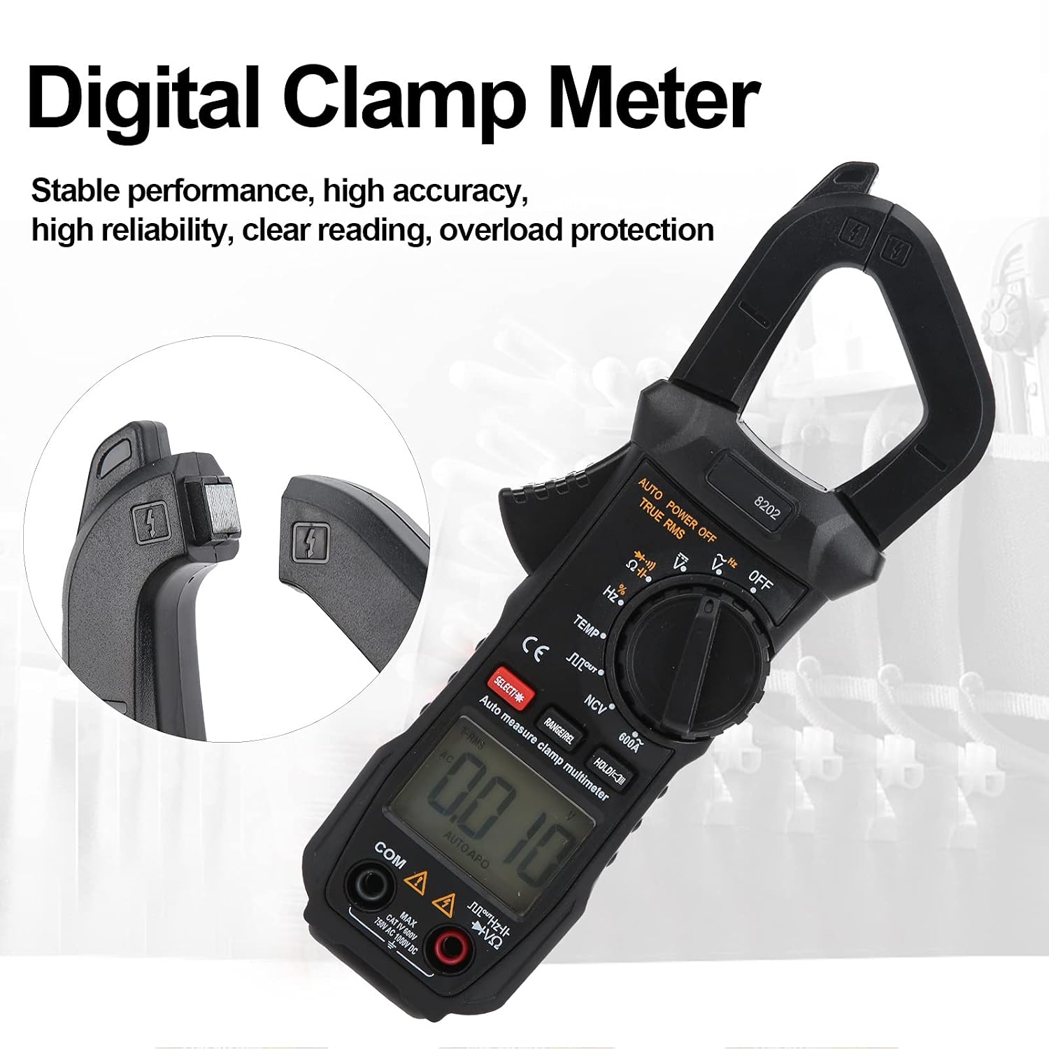
Figure 4.2: Close-up view of the clamp jaw and LCD display of the Klanata ET8202 Digital Clamp Meter, showing the '8202' model number and measurement readings.

Figure 4.3: Front and back views of the Klanata ET8202 Digital Clamp Meter, displaying the serial number on the rear and safety warnings.
- Clamp Jaw: Used for non-contact AC current measurement.
- Trigger: Opens the clamp jaw.
- Function Dial: Selects the desired measurement mode.
- LCD Display: Shows measurement readings, units, and indicators.
- SELECT Button: Toggles between functions within a single dial position (e.g., Diode/Continuity).
- RANGE/REL Button: Manually selects measurement range or activates relative measurement mode.
- HOLD Button: Freezes the current reading on the display.
- Input Jacks (VΩHz, COM): Connect test leads for voltage, resistance, capacitance, frequency, and temperature measurements.
- Flashlight: Provides illumination for working in dimly lit areas.
5. Setup
5.1 Battery Installation
The ET8202 requires two 1.5V AAA batteries for operation.
- Locate the battery compartment on the back of the meter (refer to Figure 4.3).
- Use a screwdriver to open the battery cover.
- Insert the two AAA batteries, ensuring correct polarity (+/-) as indicated inside the compartment.
- Securely close the battery cover and fasten the screw.
5.2 Connecting Test Leads
For most measurements, test leads are required.
- Insert the red test lead into the "VΩHz" input jack.
- Insert the black test lead into the "COM" (common) input jack.
- For temperature measurements, connect the thermal contact probe to the "VΩHz" and "COM" input jacks.
6. Operating Instructions
6.1 Power On/Off
To power on the meter, rotate the function dial from the "OFF" position to any desired measurement function. To power off, rotate the dial back to "OFF". The meter features an auto power-off function to conserve battery life.
6.2 Function Selection
Rotate the central function dial to select the desired measurement mode. Use the SELECT button to toggle between specific functions within a single dial position (e.g., AC/DC voltage, Diode/Continuity).
6.3 Measurement Procedures
- AC Voltage Measurement (V~):
- Set the function dial to V~.
- Connect the red and black test leads in parallel to the circuit or component under test.
- Read the AC voltage value on the LCD.
- DC Voltage Measurement (V-):
- Set the function dial to V-.
- Connect the red and black test leads in parallel to the circuit or component under test.
- Read the DC voltage value on the LCD.
- AC Current Measurement (A~):
- Set the function dial to A~ (600A range).
- Open the clamp jaw by pressing the trigger.
- Enclose a single conductor (not a cable with multiple conductors) within the clamp jaw.
- Ensure the jaw is fully closed.
- Read the AC current value on the LCD.
- Resistance Measurement (Ω):
- Set the function dial to Ω.
- Ensure the circuit or component is de-energized before testing.
- Connect the test leads across the component.
- Read the resistance value on the LCD.
- Capacitance Measurement (F):
- Set the function dial to F.
- Ensure the capacitor is fully discharged before testing.
- Connect the test leads across the capacitor terminals.
- Read the capacitance value on the LCD.
- Frequency Measurement (Hz):
- Set the function dial to Hz.
- Connect the test leads to the signal source.
- Read the frequency value on the LCD.
- Temperature Measurement (TEMP):
- Set the function dial to TEMP.
- Connect the thermal contact probe to the meter's input jacks.
- Place the tip of the probe on the object or area to be measured.
- Read the temperature value on the LCD.
- Non-Contact Voltage (NCV) Detection:
- Set the function dial to NCV.
- Bring the top of the clamp meter near a live AC voltage source.
- The meter will indicate the presence of AC voltage through an audible beep and/or visual indicator.
- Diode Test / Continuity:
- Set the function dial to the diode/continuity symbol.
- For diode test, connect leads across the diode.
- For continuity, connect leads across the circuit. An audible tone indicates continuity.
6.4 Special Functions
- SELECT Button: Used to switch between functions within a single dial position (e.g., Diode/Continuity, AC/DC in some modes).
- RANGE/REL Button: Used to manually select measurement range or activate relative measurement mode.
- HOLD Button: Freezes the current reading on the display. Press again to release.
7. Maintenance
7.1 Cleaning
- Wipe the meter with a damp cloth and mild detergent. Do not use abrasive cleaners or solvents.
- Ensure the meter is completely dry before storage or subsequent use.
7.2 Battery Replacement
When the low battery indicator appears on the display, replace the batteries promptly to ensure accurate readings and proper device function. Follow the battery installation steps outlined in Section 5.1.
7.3 Storage
- Store the meter in a cool, dry place, away from direct sunlight and extreme temperatures.
- Remove batteries if the meter will not be used for an extended period to prevent potential leakage and damage.
8. Troubleshooting
- No Display / Meter Not Turning On:
- Check battery installation and polarity.
- Replace batteries if they are low or depleted.
- Ensure the function dial is not set to "OFF".
- Inaccurate Readings:
- Ensure test leads are properly connected and not damaged.
- Verify the correct function and range are selected.
- Check for external interference (e.g., strong magnetic fields).
- Ensure the clamp jaw is fully closed for current measurements.
- "OL" Display:
- Indicates an over-range condition. The measured value exceeds the selected range or the meter's maximum capability.
- Select a higher range if available, or confirm the measurement is within the meter's specifications.
- No Continuity Beep:
- Ensure the meter is set to continuity mode.
- Check test leads for damage or poor connection.
- The circuit may not have continuity.
9. Specifications
| Parameter | Value |
|---|---|
| Item Type | Clamp Multimeter |
| Model | ET8202 |
| Material | ABS |
| Power Supply | 2 x 1.5V AAA (Battery Not Included) |
| Maximum Display | 5999 (5 5/6) Digits |
| Automatic Polarity Display | Yes |
| Measurement Method | Double Integral A/D Conversion |
| Sampling Rate | About 3 times per second |
| Over-Range Display | "OL" |
| Working Environment | (0~40)℃ Relative Humidity |
| AC Voltage | 750V |
| DC Voltage | 1000V |
| AC Current | 600A |
| Frequency | 10MHz |
| Resistance | 40MΩ |
| Capacitance | 30mF |
| Temperature | (-20~1000)℃ |
| Jaw Opening | Approx. 27mm / 1.1in |
10. Warranty and Support
For detailed warranty information, technical support, or service inquiries, please refer to the contact details provided with your purchase documentation or visit the official Klanata website. Keep your purchase receipt as proof of purchase for warranty claims.