1. Introduction
This manual provides essential information for the safe and efficient operation of your PowMr 4000W Hybrid Solar Inverter. This device is designed to convert 24VDC battery power into 110/120VAC pure sine wave electricity, integrating a 140A MPPT charge controller for optimal solar energy utilization. It supports various battery types and off-grid system configurations. Please read this manual thoroughly before installation and use, and retain it for future reference.
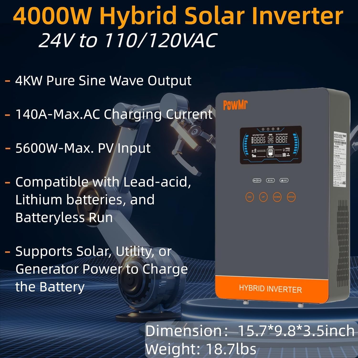
Image: The PowMr 4000W Hybrid Solar Inverter, highlighting its 4KW pure sine wave output, 140A max AC charging current, 5600W max PV input, compatibility with various batteries, and support for solar, utility, or generator power to charge the battery. Dimensions are 15.7"L x 9.8"W x 3.5"H and weight is 18.7lbs.
2. Safety Instructions
Always observe the following safety precautions to reduce the risk of electric shock, fire, or injury:
- Installation must be performed by qualified personnel.
- Ensure all wiring is correctly sized and properly insulated.
- Do not disassemble the inverter. There are no user-serviceable parts inside.
- Keep the inverter away from flammable materials, moisture, and direct sunlight.
- Ensure adequate ventilation around the inverter to prevent overheating.
- Always disconnect all power sources (PV, battery, AC input) before performing any maintenance or wiring.
- Wear appropriate personal protective equipment (PPE) during installation and maintenance.
3. Product Overview
3.1. Features
- Pure Sine Wave Output: Provides stable and clean power suitable for sensitive electronics.
- Integrated MPPT Charge Controller: 140A MPPT for efficient solar charging.
- Wide Battery Compatibility: Supports AGM, Gel, Lead-acid, Lithium-ion, and LiFePO4 batteries.
- Batteryless Mode: Can power loads directly from PV/AC grid without a connected battery.
- Multiple Charging Modes: Solar Only, Mains Only, Mains & Solar Hybrid.
- Multiple Load Output Modes: Utility Priority, Solar Priority, Solar and SBU Priority.
- Advanced Protection: Short circuit, over voltage, under voltage, overload, reverse polarity, over-temperature, and backfill protection.
- User-Friendly Interface: 6.25-inch LCD screen with touch controls for real-time data display.
- Communication Ports: RS485 and RS232 for monitoring and control.
3.2. Component Identification

Image: A detailed diagram of the PowMr Hybrid Solar Inverter, showing its front panel and connection ports. Key components labeled include: 1. LCD display, 2. Status indicator, 3. Charging indicator, 4. Fault indicator, 5. Function touch buttons, 6. On/off switch, 7. AC input, 8. AC output, 9. PV input, 10. Battery input, 11. RS485/RS232 communication port.
3.3. Protection Features

Image: An illustration detailing the comprehensive protection features of the inverter, including Short Circuit Protection, Over-Load Protection, Over Current Protection, Backfill Protection, Over Voltage Protection, Over-Temperature Protection, Under Voltage Protection, and Over Charge Protection.
4. Package Contents
Upon unpacking, please verify that all items are present and undamaged:
- PowMr 4000W Hybrid Solar Inverter
- Instruction Manual (this document)
- Communication Cables (if applicable, check packaging)
- Mounting Hardware (if applicable, check packaging)
5. Installation and Setup
5.1. Mounting the Inverter
Select a suitable location for mounting the inverter. It should be:
- Indoors, protected from direct sunlight, rain, and dust.
- Well-ventilated to allow for heat dissipation.
- Close to the battery bank to minimize cable length and voltage drop.
- On a solid, non-flammable surface.
5.2. Wiring Diagram
Follow the wiring diagram carefully. Incorrect wiring can cause damage to the inverter, batteries, or connected loads, and may pose a safety hazard.

Image: A comprehensive wiring diagram illustrating connections for PV input, Mains/Generator input, AC output, and Battery input. It specifies voltage ranges, current ratings, and recommended wire gauges for each connection point.
5.3. Battery Connection
The inverter is compatible with various 24V battery types. Ensure your battery bank matches the inverter's voltage requirements.

Image: An illustration showing the inverter's compatibility with various battery types including AGM, GEL, FLD (Flooded), LI (Lithium-ion), SLD (Sealed Lead-Acid), and USER-defined settings. It also indicates a maximum battery charging current of 140A (utility charging + solar charging).
- Connect the battery cables to the inverter's battery terminals, ensuring correct polarity (positive to positive, negative to negative).
- Tighten all connections securely.
5.4. PV Array Connection
- Connect the solar panel array to the PV input terminals, observing correct polarity.
- Ensure the PV array's open circuit voltage and power are within the inverter's specifications.
5.5. AC Input/Output Connection
- Connect the AC utility grid or generator to the AC input terminals.
- Connect your AC loads to the AC output terminals.
- Ensure all AC connections are properly grounded.
6. Operating Instructions
6.1. Powering On/Off
- To Power On: Ensure all connections are secure. First, connect the battery, then the PV array, and finally the AC input. Press the On/Off switch.
- To Power Off: Disconnect the AC input, then the PV array, and finally the battery. Press the On/Off switch.
6.2. LCD Display and Controls
The LCD screen displays real-time system data. Use the touch buttons to navigate menus and adjust settings.
6.3. Setting Charging and Output Modes
The inverter offers flexible charging and output modes to suit various energy management needs.

Image: An illustration detailing the three charging modes (1. Only Solar, 2. Only Utility, 3. Solar+Utility) and three output modes (1. Utility First, 2. Solar First (default), 3. SBU priority). Steps to set programs are also provided: 1. Long press and hold ENTER button for 3s, 2. Press UP and DOWN to select setting programs, 3. Press ENTER to confirm or ESC to exit.
6.3.1. Charging Modes
- Solar Only: Charges batteries exclusively from solar panels.
- Mains Only: Charges batteries exclusively from the AC utility grid or generator.
- Mains & Solar Hybrid: Prioritizes solar charging, supplementing with AC utility/generator if solar power is insufficient.
6.3.2. Load Output Modes
- Utility Priority: Loads are primarily powered by the AC utility grid. Inverter switches to battery/solar if utility fails.
- Solar Priority: Loads are primarily powered by solar and battery. Inverter switches to utility if solar/battery power is insufficient.
- SBU Priority (Solar-Battery-Utility): Loads are primarily powered by solar, then battery, and finally by utility as a last resort.
7. Maintenance
Regular maintenance ensures optimal performance and longevity of your inverter.
- Cleaning: Periodically clean the inverter's exterior with a dry cloth. Do not use liquid cleaners.
- Ventilation: Ensure cooling fan vents are clear of dust and obstructions. The triple cooling fan design helps dissipate heat efficiently.
- Connections: Annually check all electrical connections for tightness and signs of corrosion.
- Environment: Maintain a clean, dry, and well-ventilated environment around the inverter. The dust-proof design helps prevent dust ingress.
8. Troubleshooting
If you encounter issues, refer to the following common problems and solutions. For persistent issues, contact customer support.
| Problem | Possible Cause | Solution |
|---|---|---|
| Inverter not turning on | No battery connection; Low battery voltage; On/Off switch off | Check battery connections; Charge battery; Turn on switch |
| No AC output | Overload; Short circuit; Inverter fault | Reduce load; Check for short circuits; Restart inverter |
| PV charging not working | PV array disconnected; Insufficient sunlight; PV voltage too low/high | Check PV connections; Ensure adequate sunlight; Verify PV array specifications |
| Overload warning | Connected loads exceed inverter capacity | Disconnect some loads; Ensure total load is within 4000W |
| High temperature warning | Poor ventilation; Ambient temperature too high | Clear vents; Improve airflow; Relocate inverter if necessary |
9. Specifications
Technical specifications for the PowMr 4000W Hybrid Solar Inverter:
| Parameter | Value |
|---|---|
| Model Number | POW-LVM4K-24V-FBA2 |
| Rated Output Power | 4000W |
| Input Voltage (DC) | 24VDC |
| Output Voltage (AC) | 110/120VAC |
| Output Waveform | Pure Sine Wave |
| Max. PV Open Circuit Voltage | 350VDC |
| PV Array MPPT Voltage Range | 55-350VDC |
| Max. PV Input Power | 5600W |
| Rated Grid Input Voltage | 110/120VAC |
| Max. Hybrid Charging Current (AC+PV) | 140A |
| Communication | RS485, RS232 |
| Display Type | LCD |
| Dimensions (L x W x H) | 15.7"L x 9.8"W x 3.5"H |
| Weight | 18.7 lbs (approximate, derived from image) |
10. Warranty and Support
10.1. Warranty Information
The PowMr 4000W Hybrid Solar Inverter comes with an 18-month warranty from the date of purchase. This warranty covers defects in materials and workmanship under normal use. It does not cover damage caused by improper installation, misuse, accidents, unauthorized modifications, or natural disasters.
10.2. Customer Support
For technical assistance, warranty claims, or any questions regarding your PowMr inverter, please contact PowMr customer support through the retailer's platform or the official PowMr website. Please have your model number (POW-LVM4K-24V-FBA2) and purchase date available when contacting support.