1. Product Overview
This Jieotwice Oval Gear Flow Meter is designed for precise measurement of fluid flow. It features a robust stainless steel valve body, a sensitive flow rotor assembly, and an integrated Hall effect sensor. The meter is suitable for detecting fluid flow in various industrial applications, ensuring high precision and reliability.
- Constructed with a stainless steel valve body, flow rotor assembly, and Hall effect sensor.
- Designed for installation at the inlet of heating systems or similar equipment to detect fluid flow.
- Operates by a magnetic rotor that rotates proportionally to the fluid flow rate.
- The Hall sensor generates pulse signals for flow rate calculation and regulation by a controller.
- Applicable in flow control settings such as gas stations, petroleum chemical plants, refineries, and tank trucks.
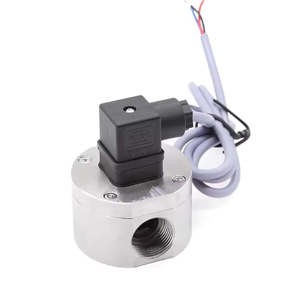
Figure 1: General view of the Jieotwice Stainless Steel Oval Gear Flow Meter.
2. Specifications
| Parameter | Value |
|---|---|
| Product Name | Oval Gear Flow Meter |
| Valve Body Material | Stainless Steel |
| Operating Voltage | DC 3.5-24V |
| Inner Diameter | 24.5mm |
| Maximum Operating Current | 15mA (at DC 5V) |
| Load Capacity | ≤10mA (at DC 5V) |
| Allowable Pressure | ≤1.0MPa |
| Flow Range | 30-3000 L/H ± 2% |
| Thread Size | G3/4” |
| Model Number | JT26-0224-73 |
| Manufacturer | Jieotwice |
3. Setup and Installation
Follow these steps for proper installation of your flow meter:
- Unpacking: Carefully remove the flow meter from its packaging and inspect it for any signs of damage. Ensure all components are present.
- Mounting: Install the flow meter at the inlet of the system where fluid flow detection is required. Ensure the G3/4” thread is securely connected to the piping. The meter should be installed in a position that allows for unobstructed fluid flow and easy access for wiring.
- Electrical Connection: Connect the Hall effect sensor to a DC 3.5-24V power source and a compatible controller. Refer to the wiring diagram for correct connections. The maximum operating current is 15mA (at DC 5V) and load capacity is ≤10mA (at DC 5V).
- System Integration: Integrate the pulse signals from the Hall sensor into your control system for flow rate calculation and regulation.

Figure 2: Flow meter showing the G3/4” threaded connection.

Figure 3: Electrical wiring connections for the Hall effect sensor.
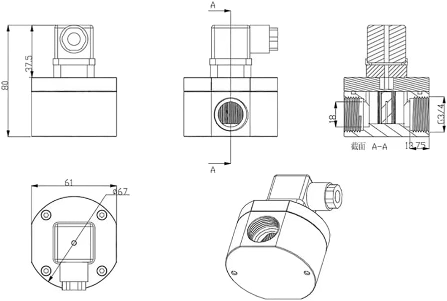
Figure 4: Technical drawing with dimensions for installation planning.
4. Operating Instructions
The flow meter operates by detecting the rotation of an internal magnetic rotor. As fluid passes through the meter, the rotor spins at a speed directly proportional to the flow rate. The integrated Hall effect sensor converts this rotational speed into electrical pulse signals.
These pulse signals are then transmitted to a connected controller. The controller interprets these pulses to calculate the precise fluid flow rate, allowing for accurate monitoring and regulation within your system. Ensure your controller is properly configured to receive and interpret the pulse signals from the flow meter.
5. Maintenance
Regular maintenance ensures the longevity and accuracy of your flow meter:
- Regular Inspection: Periodically inspect the flow meter for any signs of wear, corrosion, or damage, especially around the connections and sensor housing.
- Cleaning: Ensure the fluid path remains clear of debris. If necessary, disconnect the meter and flush it with a compatible cleaning solution. Avoid using abrasive materials or harsh chemicals that could damage the stainless steel body or internal components.
- Connection Integrity: Verify that all electrical and pipe connections are secure and free from leaks or loose wiring. Loose connections can lead to inaccurate readings or operational failure.
- Fluid Compatibility: Ensure that the fluids being measured are compatible with stainless steel to prevent corrosion and extend the life of the meter.
6. Troubleshooting
If you encounter issues with your flow meter, refer to the following troubleshooting guide:
- No Flow Reading:
- Check power supply to the Hall sensor (DC 3.5-24V).
- Verify electrical connections are secure and correct.
- Inspect for blockages in the fluid path or a stuck rotor.
- Ensure fluid is actually flowing through the meter.
- Inaccurate Flow Reading:
- Confirm the flow meter is installed correctly and oriented for proper flow.
- Check for air bubbles or cavitation in the fluid stream.
- Verify the controller's calibration settings are correct for the meter's pulse output.
- Inspect for internal damage or debris affecting rotor movement.
- Leaks at Connections:
- Tighten pipe connections. Use appropriate thread sealant if necessary.
- Inspect gaskets or O-rings for damage and replace if needed.
7. Warranty and Support
For warranty information, technical support, or service inquiries, please contact the manufacturer, Jieotwice, or the seller directly. Refer to your purchase documentation for specific warranty terms and contact details.
Seller: Jieotwice-CA